Direct injection controller settings – Ag Leader EDGE Ver.4.5 Users Manual User Manual
Page 155
143
A
PPLICATION
20. Enter Suggested Name for Configuration
If desired, use the keyboard button to edit the suggested configuration name. Press the green check mark
button and continue with the procedure.
21. Complete the configuration procedure
At the Add Equipment for Dual Product Application screen, press the blue right-arrow button. Continue
through the wizard by entering a Ground Speed Source and then entering a suggested name for your
operating configuration.
D
IRECT
I
NJECTION
C
ONTROLLER
S
ETTINGS
The settings contained on this controller settings screen determine Direct Injection product pump
performance. To view the Direct Injection Controller Settings screen, press the Application button at the
Setup screen. Go to the Application Setup Controller Tab.
At the Application Setup Controller Tab, highlight your Direct
Injection module’s controller in the Controller List and press the
Setup (wrench) button.
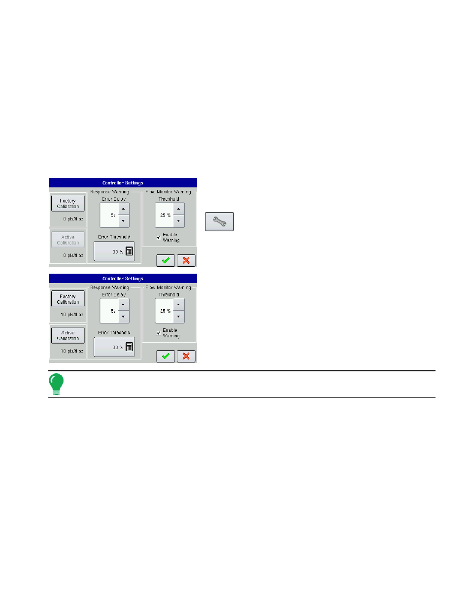
At the following screen, press the Controller Settings button.
The Controller Settings screen appears, as shown.
• Factory Calibration
This number is found on the tag of the Digital Pump Speed Sensor.
This tag number represents pulses per 10 fluid ounces. Divide the
tag number by 10 and enter this number. Once entered, this
number should not be changed.
Note: Active Calibration button becomes active once the factory calibration is entered.
• Active Calibration
Press the Perform Calibration button to begin the calibration procedure for the Direct Injection pump. The
pump will not run until this calibration has been performed. For more information, see
• Error Delay
The number of seconds that the actual rate falls out of the error threshold before an alarm sounds.
• Error Threshold
The user-defined percentage of actual rate error allowed before an alarm sounds.
• Flow Monitor Warning Threshold
The percentage of perceived application error, based on the discharge flow sensor.
• Enable Warning
The Enable Warning check box allows you the option of displaying the Flow Monitor Warning.