Ag Leader EDGE Ver.4.5 Users Manual User Manual
Page 114
102
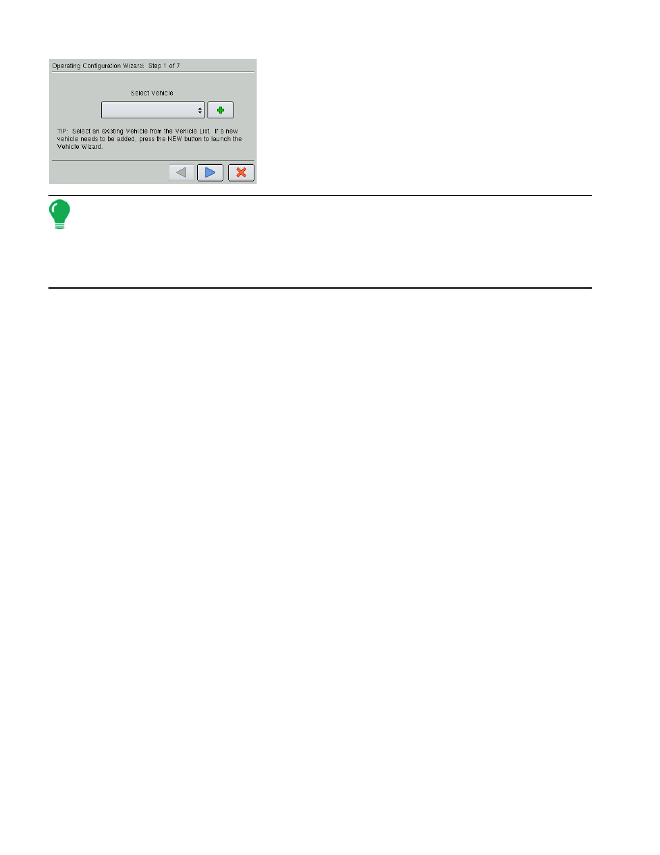
4. From here, follow the Wizard’s instructions to create a
configuration that includes Vehicle, Implement, and Controller
settings.
Note: From the Configuration Tab, you can also:
• Press the on-screen keyboard to edit or rename existing configurations.
• Press the Wrench button to access Configuration Settings. For more information, see
• Press the Remove button to remove a configuration. Caution: When deleting a configuration all data logged
with that configuration will be deleted.
5. Select Implement
Select the desired implement from the drop down list; then press the blue right-arrow button and proceed
to step 4. If your implement is not listed, press New. Select an Implement Attachment Method, Enter a Full
Swath Width, Enter the Number of Boom Sections, Enter Boom Section Widths from Left to Right, Enter
Distance from Hitch to Application Point, and Enter an Implement Name. Press the blue right-arrow button
to continue.
6. Select Operating Mode
Use the drop-down menu to select Rate Logging/Control if you are going to be creating a configuration
where an application rate is logged (such as a DirectCommand configuration). Otherwise, select Area
Logging Only if you are creating a Site Verification configuration. Press the blue right-arrow button to
continue.
• If you selected Rate Logging Control, continue at Step 5 below.
• If you selected Area Logging Only, select an Implement, and a Ground Speed Source; and then name
and save the configuration.
7. Select Controller
Select the Device and Direct Type of your configuration. Under Device, select either DirectCommand,
Serial Controller, or Flow Meter.
• If you selected DirectCommand as the Device, under Direct Type choose either:
- Liquid Product Control. From here, enter a Flow Meter Calibration number, and then name and save
the configuration. For a more detailed DirectCommand Liquid Product configuration procedure, see
“Liquid Application Control Configuration” on page
- Spinner Spreader Control 3CH or Spinner Spreader Control 5 CH. From here, name and save the
configuration. For a more detailed DirectCommand Spinner Spreader configuration procedure, see
“Spinner Spreader Control Configuration” on page
• If you entered Serial Controller as the Device, select the Make and Model of your application device,
then name and save the configuration.
• If you entered Flow Meter as the Device, use the numeric keypad to enter the Flow Meter Calibration
Number, then name and save the configuration.