Connection example with the other instruments, Connection example with the other instruments -6 – Yokogawa Data Acquisition with PID Control CX2000 User Manual
Page 86
3-6
IM 04L31A01-17E
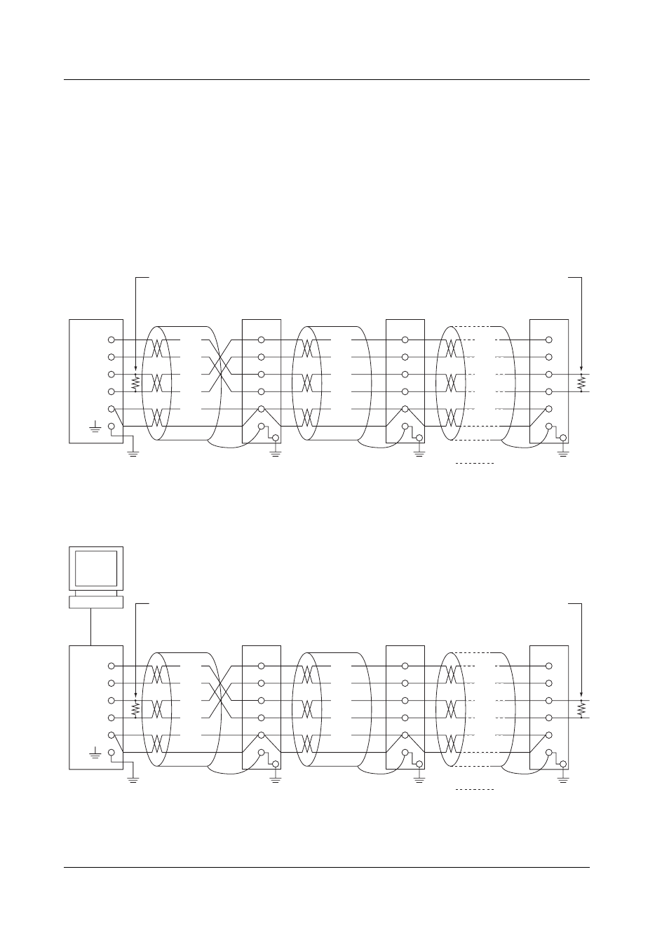
Connection Example with the Other Instruments
You can connect the CX as a host to multiple Green series controllers or connect the CX
to a host computer such as a PC.
• If the host uses an RS-232 interface, use a converter. For recommended converters,
see the latter section “Serial Interface Converter.”
• The two-wire cable can be used only when using the Modbus protocol. For the
configuration procedure, see section 3.5.
Four-Wire System
In general, the instrument and the host computer are connected with the transmission
and reception lines crossed. Terminal instruments are connected to each other using
straight connections.
Terminator (externally attached) 120 Ω, 1/2 W or more
#1
Do not connect terminators to #1 through #n-1.
RS-422/485
pins on the
CX
#2
#n
(#n ≤ 32)
Terminator (externally attached)
Host
computer
SG
RDB( + )
RDA( - )
SDB( + )
SDA( - )
FG
SG
RD B
RD A
SD B
SD A
(SG)
(RD B)
(RD A)
(SDB)
(SDA)
FG
SG
RD B
RD A
SD B
SD A
(SG)
(RD B)
(RD A)
(SDB)
(SDA)
FG
SG
RD B
RD A
SD B
SD A
(SG)
(RD B)
(RD A)
(SDB)
(SDA)
The following diagram illustrates the case when the host computer’s interface is RS-232.
Terminator (externally attached) 120 Ω, 1/2 W or more
#1
Do not connect terminators to #1 through #n-1.
RS-422/485
pins on the
CX
#2
#n
(#n ≤ 32)
Terminator (externally attached)
SHIELD
RD( + )
RD( - )
TD( + )
TD( - )
FG
SG
RD B
RD A
SD B
SD A
Host
computer
Converter
(SG)
(RD B)
(RD A)
(SDB)
(SDA)
FG
SG
RD B
RD A
SD B
SD A
(SG)
(RD B)
(RD A)
(SDB)
(SDA)
FG
SG
RD B
RD A
SD B
SD A
(SG)
(RD B)
(RD A)
(SDB)
(SDA)
RS-232
3.3 Terminal Arrangement and Signal Names and the Connection Procedure of the RS-422/485 Interface