Yokogawa Data Acquisition with PID Control CX2000 User Manual
Page 224
7-32
IM 04L31A01-17E
Expansion DI01–3 (4 bytes)
bit0:
DI 0 (1:ON, 0:OFF)
bit1:
DI 1 (1:ON, 0:OFF)
:
bit11:
DI 11 (1:ON, 0:OFF)
bit12–bit 15:0
bit16:
DO 0 (1:ON, 0:OFF)
bit17:
DO 1 (1:ON, 0:OFF)
:
bit27:
DO 11 (1:ON, 0:OFF)
bit28–bit 31:0
Expansion DI02 and expansion DI03 are all 0
Internal Switches (Groups 1–6, 1 Byte)
bit0:
SW001 (1:ON, 0:OFF)
bit1:
SW002 (1:ON, 0:OFF)
:
bit5:
SW006 (1:ON, 0:OFF)
bit6, bit7:0
Divide up internal switches into groups of 6
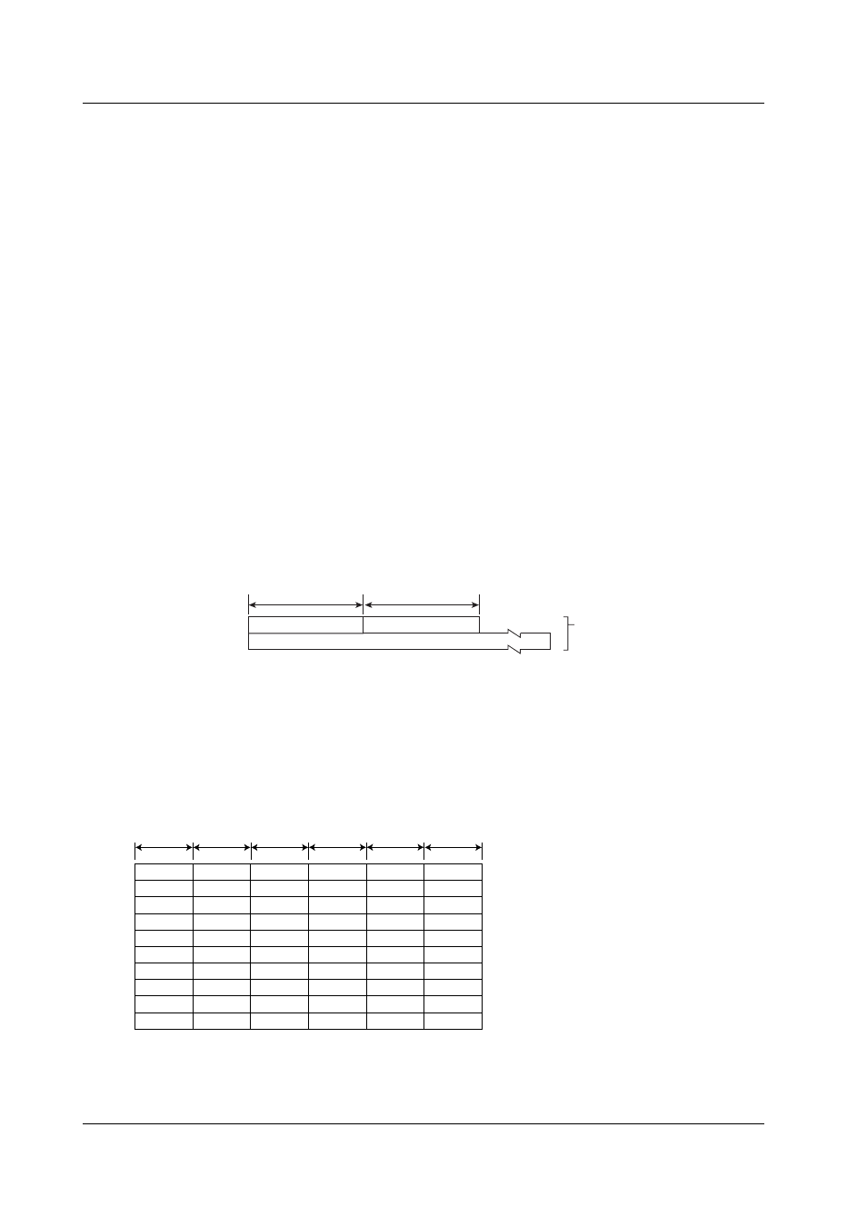
Status (Active/Inactive) of DIO Operation Monitoring Function Operation Mode (Style
Number 3 or Later)
• The status of DI/DO operation monitoring function is output using an FO command.
• The output format identifier is 1. See page 7-3, “Identifier.”
2 bytes
Number of blocks
Block 1
Number of bytes
2 bytes
BINARY data
(The BINARY data section
on the “Conceptual diagram”
on page 7-2.)
Number of Blocks
This is the number of blocks (fixed at 0.)
Number of Bytes
This is the size of one block in bytes.
Blocks
CX2000
DIO1-6
DIO1
DIO7
DIO13
DIO19
DIO25
DIO31
DIO1-6
DIO1-6
DIO1-6
DIO7-12
DIO2
DIO8
DIO14
DIO20
DIO26
DIO32
DIO7-12
DIO7-12
DIO7-12
DIO13-18
DIO3
DIO9
DIO15
DIO21
DIO27
DIO33
DIO13-18
DIO13-18
DIO13-18
DIO19-24
DIO4
DIO10
DIO16
DIO22
DIO28
DIO34
DIO19-24
DIO19-24
DIO19-24
DIO25-30
DIO5
DIO11
DIO17
DIO23
DIO29
DIO35
DIO25-30
DIO25-30
DIO25-30
DIO31-36
DIO6
DIO12
DIO18
DIO24
DIO30
DIO36
DIO31-36
DIO31-36
DIO31-36
Status (Active/Inactive) of DIO operation
monitoring function
1 byte
1 byte
1 byte
1 byte
1 byte
1 byte
DIO type
DIO type
DIO type
DIO type
DIO type
DIO type
Operation setting of DIO operation monitoring function
Status of DIO operation monitoring function input
Status of DIO operation monitoring functionoutput
7.3 Output Format of BINARY Data