Response, Response -6 – Yokogawa Data Acquisition with PID Control CX2000 User Manual
Page 116
5-6
IM 04L31A01-17E
• 0
This position is fixed to 0.
• 5
th
digit
The most significant digit when using 5-digit notation.
• R/W
Specifies whether the command is a write command or a read command.
0: Read
1: Write
• +/–
0: Posive data (+)
1: Negative data (–)
• Read and write data
Specifies the number of data points to be read when reading.
Specifies the data to be written using 4-digit BCD excluding the decimal point when
writing.
• CR, LF
Control code indicating the end of a command.
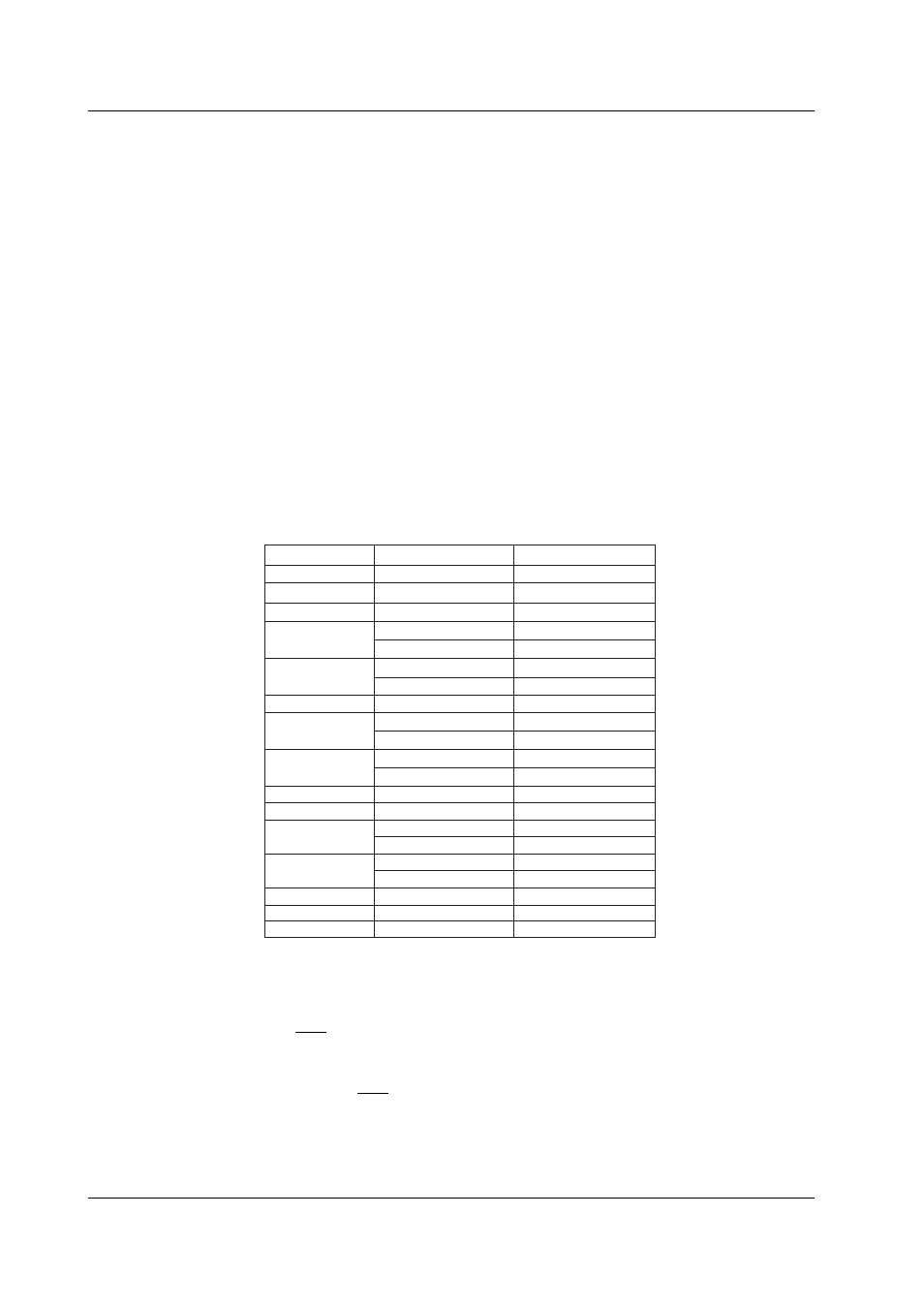
Response
The following figure illustrates the construction of responses that the CX returns.
Response against a read command
Number of BCD Digits
Command Element
2
2
4
1
1
1
1
4
1
1
Station number
CPU number (01)
D register number
0
5th digit
0
+/–
Data 1
0
5th digit
1
1
0
+/–
4
Data 2
1
1
0
5th digit
1
1
0
+/–
4
Data n
2
CR(0D)
Number of Bytes
1
1
2
1
1
2
1
1
2
1
1
2
1
1
2
LF(0A)
:
:
:
Example
Command for reading the 3
rd
channel (D register 0003) of the communication register
data of station number 01
01010003000000010D0A
Response when the measured value of 200 (BCD code) is returned against the
command above
01010003000002000D0A
5.3 Communications with PLCs