3 communications with plcs, Command construction – Yokogawa Data Acquisition with PID Control CX2000 User Manual
Page 115
5-5
IM 04L31A01-17E
5
Ladder Communication Protocol
5.3
Communications with PLCs
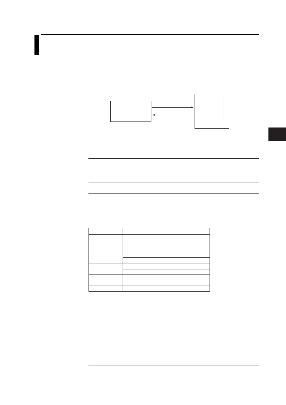
When performing ladder communications, make sure the PLC (host) first sends a
command to the CX. When the CX receives a command from a PLC, the CX executes
the specified operation, provided that no errors are present in the received command,
and returns a response to the PLC. If an error is present in the command, the CX
returns an error code corresponding to the error type to the PLC.
Command
Response
CX
PLC
The PLCs that the CX can communicate with are those that support the ladder
communication protocol.
Connectable PLCs are indicated below.
Distributor
Product Name
Requirements
YOKOGAWA
FA500
With communication module (RZ91-0N)
FA-M3
With communication module (F3RZ91-0N)
Mitsubishi Electric Corporation MELSEC-A Series
With computer link module
and others
Others
PLCs that can use the With module for RS-232 or RS-422/485
non-procedural mode
For information on the PLCs, contact the respective distributor. For details, refer to the instruction
manual for the PLC to be connected.
Command Construction
The figure below illustrates the construction of the commands that PLCs transmit.
Number of Bytes Number of BCD Digits
Command Element
1
1
2
1
1
2
1
1
2
2
4
1
1
1
1
4
2
2
Station number
CPU number (01)
D register number
0
5th digit
R/W
+/–
Read and write data
CR
LF
• Station number (1-32)
The number used by the PLC to identify the communication destination. The serial
interface address of the CX to which commands are sent is specified here.
• CPU number
Fixed to “01”.
• D register number
The D register number is specified using a 4-digit BCD value excluding the “D”.
Note
In ladder communications, the D register number is specified using BCD codes. BCD is a
method of using 4 bits to represent the decimal digits 0 through 9. For example, the value 99
expressed using 1-byte BCD code is “10011001” (not “01100011”).