Yokogawa Data Acquisition with PID Control CX2000 User Manual
Page 223
7-31
IM 04L31A01-17E
7
Response
DI/DO Data and Internal Switch Status (Style Number S3 Or Later)
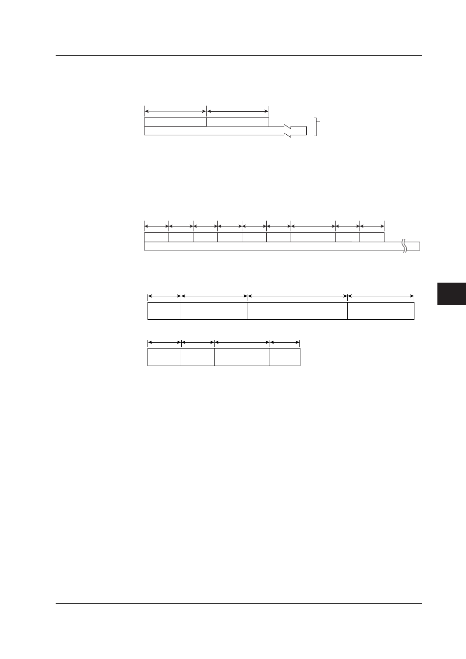
• DI/DO data and the internal switch status can be output using an FN command.
• The output format identifier is 1. See page 7-3, “Identifier.”
2 bytes
Number of blocks
Block 1
Number of bytes
2 bytes
BINARY data
(The BINARY data section
on the “Conceptual diagram”
on page 7-2.)
Number of Blocks
This is the number of blocks (fixed at 0.)
Number of Bytes
This is the size of one block in bytes.
Block
Year
Month
Day
Hour
Minute
Millisecond
(Reserved)*
Flags
Second
2 Bytes
Status of DI/DO Data and Internal Switches
1 Byte 1 Byte 1 Byte 1 Byte 1 Byte 1 Byte
1 Byte 1 Byte
Status of DI/DO data and internal switches
Mounting
information
Control
DIO1 to 3
Internal switches
Gr 1 to 6
2 bytes
2 bytes X 3=6 bytes
4 bytes X 3=12 bytes
1 byte X 6=6 bytes
CX2000
2 bytes
2 bytes
1byte X 3=3 bytes
CX1000
1byte
Expansion DIO1 to 3
Mounting
information
Control
DIO1
Internal switches
Gr 1 to 6
(Reserved)*
* The sections indicated as (Reserved) are not used. The value is fixed to “0.”
Data details
Mounting information (2 bytes)
bit0:
control module 1 Mounted (1), not Mounted (0)
bit1:
control module 2 Mounted (1), not Mounted (0)
bit2:
control module 3 Mounted (1), not Mounted (0)
bit3:
0
bit4:
expansion module 1 Mounted (1), not Mounted (0)
bit5:
0
bit6:
0
bit7–bit 15:
0
Control DI01–3 (2 bytes)
bit0:
DI 0 (1:ON, 0:OFF)
bit1:
DI 1 (1:ON, 0:OFF)
:
bit5:
DI 6 (1:ON, 0:OFF)
bit6–bit7:
0
bit8:
DO 0 (1:ON, 0:OFF)
bit9:
DO 1 (1:ON, 0:OFF)
:
bit13:
DO 6 (1:ON, 0:OFF)
7.3 Output Format of BINARY Data