Yokogawa Data Acquisition with PID Control CX2000 User Manual
Page 228
7-36
IM 04L31A01-17E
CX1000
bit0: Loop 1 (1:assigned, 0: unassigned)
bit1: Loop 2 (1:assigned, 0: unassigned)
bit2–bit7:
0
Measurement/Computation/Control Channel Alarm Types, Output of Settings (Style
Number S3 or Later)
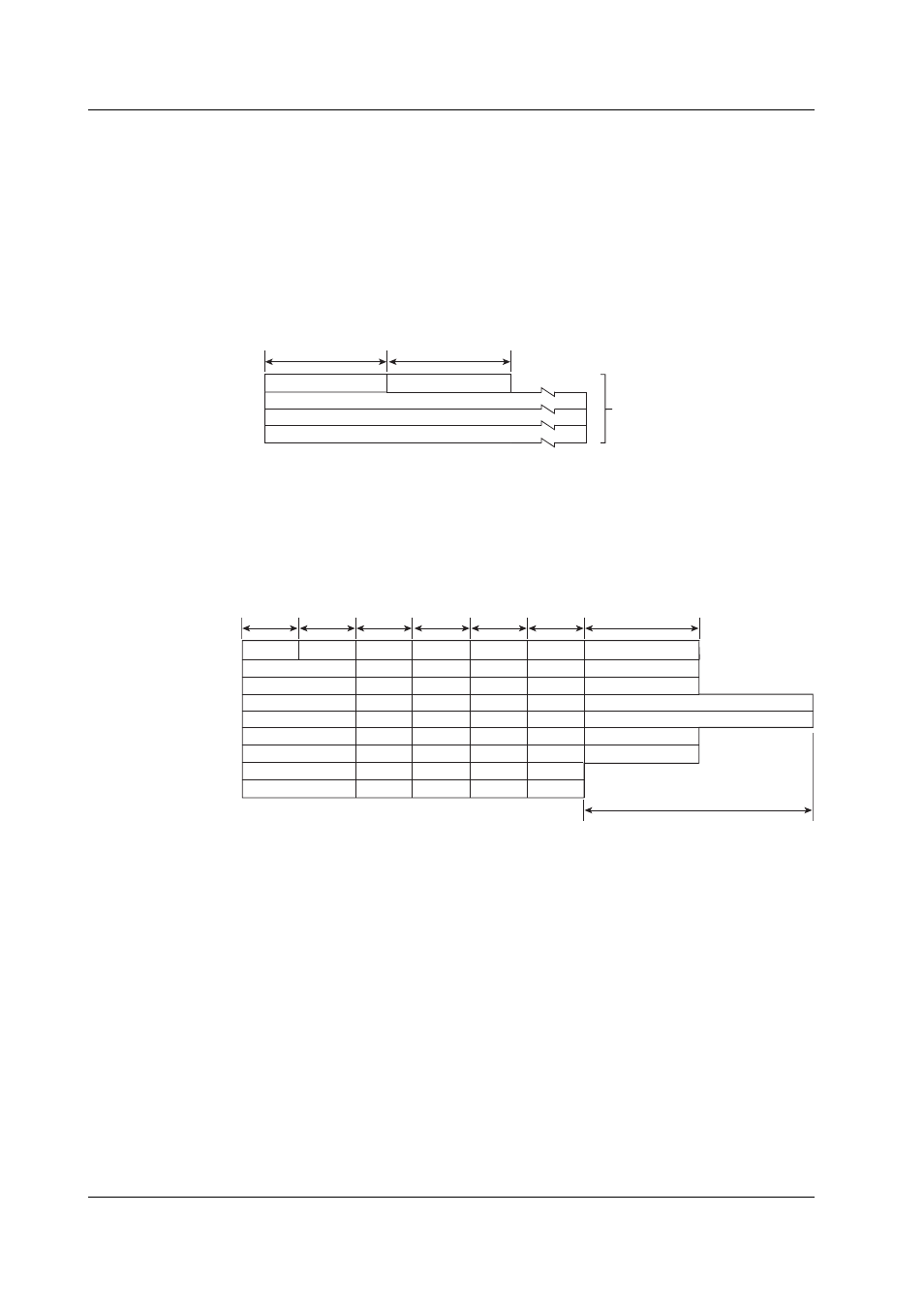
• Measurement/computation/control channel alarm types, and settings are output using
the FS command.
• The output format identifier is 1. See page 7-3, “Identifier.”
2 bytes
Number of blocks
Block 1
. . .
Block n
Number of bytes
2 bytes
BINARY data
(The BINARY data section
on the “Conceptual diagram”
on page 7-2.)
Number of Blocks
This is the number of blocks.
Number of Bytes
This is the size of one block in bytes.
Blocks
Year
Month
Day
SP
• • •
SP
• • •
SP
• • •
SP
• • •
Hour
Alarm level
• • •
Alarm level
• • •
Alarm level
• • •
Alarm level
• • •
Minute
Alarm type
• • •
Alarm type
• • •
Alarm type
• • •
Alarm type
• • •
Millisecond
Alarm settings
• • •
Alarm settings
• • •
Second
(Reserved)*
• • •
(Reserved)*
• • •
(Reserved)*
• • •
(Reserved)*
• • •
Alarm settings
• • •
1 byte
1 byte
1 byte
1 byte
1 byte
1 byte
2 bytes
4 bytes
Measurement channel
• • •
Math channel
• • •
Control channel
• • •
Channel(Green Series)
• • •
* The sections indicated as (Reserved) are not used. The value is fixed to “0.”
Data details
Channel number
CX2000:1-20, 31-60, 101-118, 201-248
CX1000:1-3, 31-48, 101-106, 201-212
SP
Target setpoint number (0 for other than control channels)1-8
The top bit of the currently used target setpoint number data is 1.
Alarm level
0-3
Alarm type
0-31
For the correspondence between the alarm type and number, see the alarm status of
“Measured/Computed/Control Data, and FIFO Data” on page 7-27.
Alarm settings
0 when the alarm type is 0 (no alarm). Not output on external temperature meter
channels.
7.3 Output Format of BINARY Data