Yokogawa Data Acquisition with PID Control CX2000 User Manual
Page 269
App-10
IM 04L31A01-17E
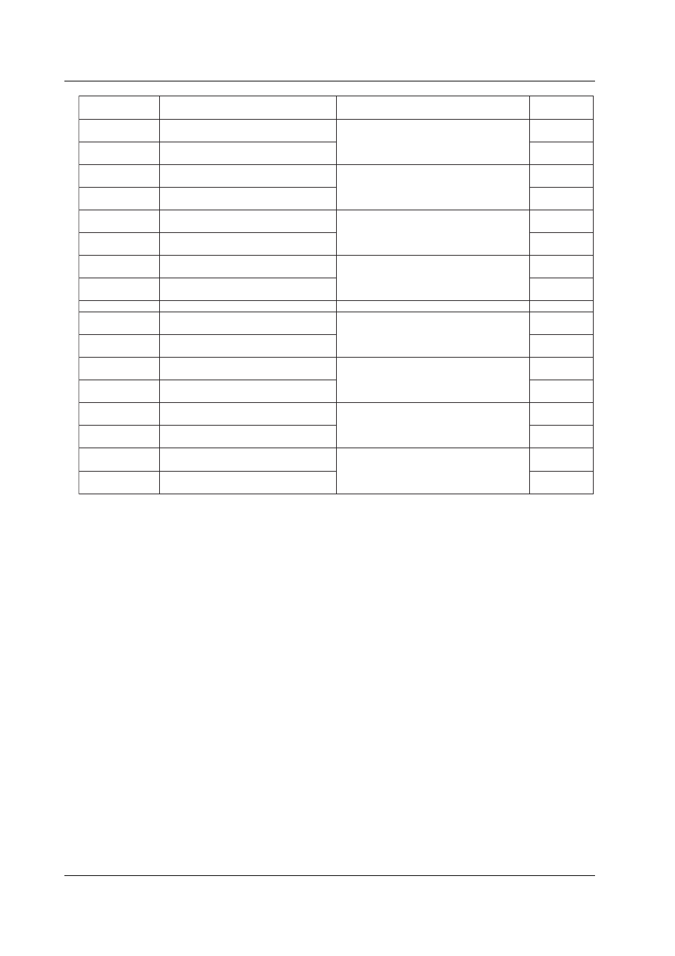
40601
40602
40603
40604
40605
40606
40607
40608
:
40833
40834
40835
40836
40837
40838
40839
40840
Alarm value of computation channel 1
Higher 2 bytes of alarm number 1
Alarm value of computation channel 1
Lower 2 bytes of alarm number 1
Alarm value of computation channel 1
Higher 2 bytes of alarm number 2
Alarm value of computation channel 1
Lower 2 bytes of alarm number 2
Alarm value of computation channel 1
Higher 2 bytes of alarm number 3
Alarm value of computation channel 1
Lower 2 bytes of alarm number 3
Alarm value of computation channel 1
Higher 2 bytes of alarm number 4
Alarm value of computation channel 1
Lower 2 bytes of alarm number 4
:
Alarm value of computation channel 60
Higher 2 bytes of alarm number 1
Alarm value of computation channel 60
Lower 2 bytes of alarm number 1
Alarm value of computation channel 60
Higher 2 bytes of alarm number 2
Alarm value of computation channel 60
Lower 2 bytes of alarm number 2
Alarm value of computation channel 60
Higher 2 bytes of alarm number 3
Alarm value of computation channel 60
Lower 2 bytes of alarm number 3
Alarm value of computation channel 60
Higher 2 bytes of alarm number 4
Alarm value of computation channel 60
Lower 2 bytes of alarm number 4
Value, obtained by combining the higher
2 bytes and lower 2 bytes, within the
computation channel span excluding the
decimal point (see the SA command)
Value, obtained by combining the higher
2 bytes and lower 2 bytes, within the
computation channel span excluding the
decimal point (see the SA command)
Value, obtained by combining the higher
2 bytes and lower 2 bytes, within the
computation channel span excluding the
decimal point (see the SA command)
Value, obtained by combining the higher
2 bytes and lower 2 bytes, within the
computation channel span excluding the
decimal point (see the SA command)
:
Value, obtained by combining the higher
2 bytes and lower 2 bytes, within the
computation channel span excluding the
decimal point (see the SA command)
Value, obtained by combining the higher
2 bytes and lower 2 bytes, within the
computation channel span excluding the
decimal point (see the SA command)
Value, obtained by combining the higher
2 bytes and lower 2 bytes, within the
computation channel span excluding the
decimal point (see the SA command)
Value, obtained by combining the higher
2 bytes and lower 2 bytes, within the
computation channel span excluding the
decimal point (see the SA command)
R/W
R/W
R/W
R/W
R/W
R/W
R/W
R/W
:
R/W
R/W
R/W
R/W
R/W
R/W
R/W
R/W
Modbus Register
Number
Description
Value
Read/Write
If a multiple write command of function code 16 is sent to the CX and the write operation
to the register by the CX fails, the write operation is stopped and error code 7 is returned.
When writing an alarm value to a computation channel, the two registers of higher 2
bytes and lower 2 bytes must be written simultaneously using the multiple register write
of function code 16. If you attempt to write only the higher 2 bytes or lower 2 bytes, error
code 7 is returned.
Appendix 6 Register Assignments