3 output format of binary data, Measured/computed/control data and fifo data – Yokogawa Data Acquisition with PID Control CX2000 User Manual
Page 218
7-26
IM 04L31A01-17E
7.3
Output Format of BINARY Data
This section describes the output format of the BINARY data that is disclosed.
For information on other BINARY data, see “Identifier” on page 7-3.
• Measured/computed/control data and FIFO data.
• Display data
• Event data
The measured/computed data is output using signed 16-bit integer; the computed data is
output using signed 32-bit integer. Physical value is derived adding the decimal point
and unit. The decimal point position can be determined using the FE command.
Example of Deriving Physical Values from Binary Data
BINARY Data
Decimal Point Position
Physical Value (Measured Value)
10000
0
10000
10000
1
1000.0
10000
2
100.00
10000
3
10.000
10000
4
1.0000
Note
The “
CRLF
” used in this section denotes carriage return line feed.
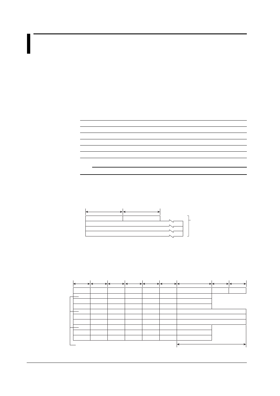
Measured/Computed/Control Data and FIFO Data
• The FD command is used to output the measured/computed/control data.
• The FF command is used to output the FIFO data.
• The ID number of the output format is “1.” See “Identifier” on page 7-3.
2 bytes
Number of blocks
Block 1
. . .
Block n
Number of bytes
2 bytes
BINARY data
(The BINARY data section
on the “Conceptual diagram”
on page 7-2.)
Number of Blocks
This is the number of blocks.
Number of Bytes
This is the size of one block in bytes.
Block
Year
. . .
. . .
. . .
. . .
. . .
. . .
Month
Channel
. . .
. . .
Channel
. . .
. . .
Channel
. . .
. . .
Day
A2
. . .
. . .
A2
. . .
. . .
A2
. . .
. . .
Hour
A1
. . .
. . .
A1
. . .
. . .
A1
. . .
. . .
Minute
A4
. . .
. . .
A4
. . .
. . .
A4
. . .
. . .
Millisecond
Measured data
. . .
. . .
Control data
. . .
. . .
(Reserved)*
Flag
Second
A3
. . .
. . .
A3
. . .
. . .
A3
. . .
. . .
Computed data
. . .
. . .
1 byte
1 byte
1 byte
1 byte
1 byte
1 byte
2 bytes
1 byte
1 byte
4 bytes
Measured/computed/control
* The sections indicated as (Reserved) are not used. The value is undefined.