Yokogawa Data Acquisition with PID Control CX2000 User Manual
Page 285
App-26
IM 04L31A01-17E
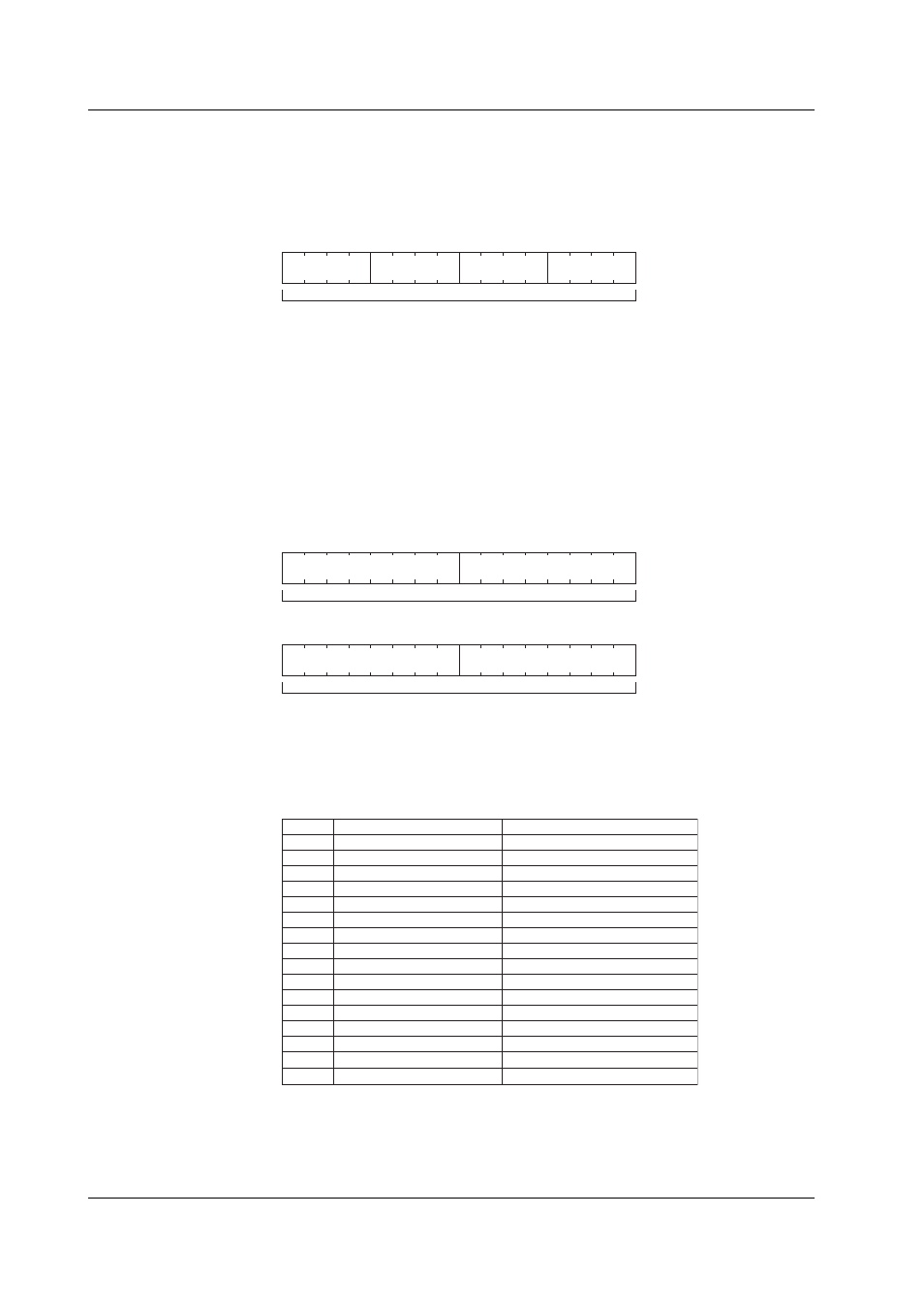
*5 The figure below shows the alarm status of the measured data and computed data. Each
register contains data in the following order: alarm number 2/alarm number 1/alarm number 4/
alarm number 3. Each alarm number uses 4 bits to specify a value in the range of 0 to 8.
Values 0 to 8 correspond to high-limit alarm, low-limit alarm, difference high-limit alarm,
difference low-limit alarm, high limit on rate-of-change alarm, low limit on rate-of-change alarm,
delay high-limit alarm, and delay low-limit alarm, respectively.
Number 2
Number 1
Number 3
Number 4
High byte
Low byte
1 word
*6 The figure below shows the alarm status of the control data. Each alarm number uses 1 byte.
Since a total of 4 bytes are used, 2 registers are used. The first register contains data in the
following order: alarm number 2/alarm number 1. The second register contains data in the
following order: alarm number 4/alarm number 3. Each alarm number uses 8 bits to specify a
value of 0 or a value in the range of 21 to 30. The value 0 corresponds to alarm OFF. Values 21
to 30 correspond to PV high-limit alarm, PV low-limit alarm, deviation high-limit alarm, deviation
low-limit alarm, deviation high & low limit alarm, deviation within high & low limits alarm (alarms
up to this point are entered in channels 101, 104, 107, and so on that indicate the PV value of
each loop), SP high-limit alarm, SP low-limit alarm (these two alarms are entered in channels
102, 105, 108, and so on that indicate the SP value of each loop), output high-limit alarm, and
output low-limit alarm (these two alarms are entered in channels 103, 106, 109, and so on that
indicate the OUT value of each loop), respectively.
Number 4
Number 3
High byte
Low byte
1 word
Number 2
Number 1
High byte
Low byte
1 word
*7 The measured data alarm statuses of registers 36001 to 36005, and the computed data alarm
statuses of registers 36006 to 36013 indicate the statuses of alarm numbers 1 to 4 of each
channel using the bit status of the register (16 bits). If the status of alarm numbers 1 to 4 of each
channel is ON, the corresponding bit is set to 1 regardless of the alarm type.
0
1
2
3
4
5
6
7
8
9
10
11
12
13
14
15
Alarm number 1 of CH01
Alarm number 2 of CH01
Alarm number 3 of CH01
Alarm number 4 of CH01
Alarm number 1 of CH02
Alarm number 2 of CH02
Alarm number 3 of CH02
Alarm number 4 of CH02
Alarm number 1 of CH03
Alarm number 2 of CH03
Alarm number 3 of CH03
Alarm number 4 of CH03
Alarm number 1 of CH04
Alarm number 2 of CH04
Alarm number 3 of CH04
Alarm number 4 of CH04
0: Alarm OFF, 1: Alarm ON
0: Alarm OFF, 1: Alarm ON
0: Alarm OFF, 1: Alarm ON
0: Alarm OFF, 1: Alarm ON
0: Alarm OFF, 1: Alarm ON
0: Alarm OFF, 1: Alarm ON
0: Alarm OFF, 1: Alarm ON
0: Alarm OFF, 1: Alarm ON
0: Alarm OFF, 1: Alarm ON
0: Alarm OFF, 1: Alarm ON
0: Alarm OFF, 1: Alarm ON
0: Alarm OFF, 1: Alarm ON
0: Alarm OFF, 1: Alarm ON
0: Alarm OFF, 1: Alarm ON
0: Alarm OFF, 1: Alarm ON
0: Alarm OFF, 1: Alarm ON
Bit
Bit Status and Alarm Status
Corresponding Alarm
Bit Configuration of Register 36001
Appendix 6 Register Assignments