Appendix 6 register assignments, Register assignments during modbus slave, Hold registers – Yokogawa Data Acquisition with PID Control CX2000 User Manual
Page 268: Appendix 6
App-9
IM 04L31A01-17E
App
Appendix
Appendix 6 Register Assignments
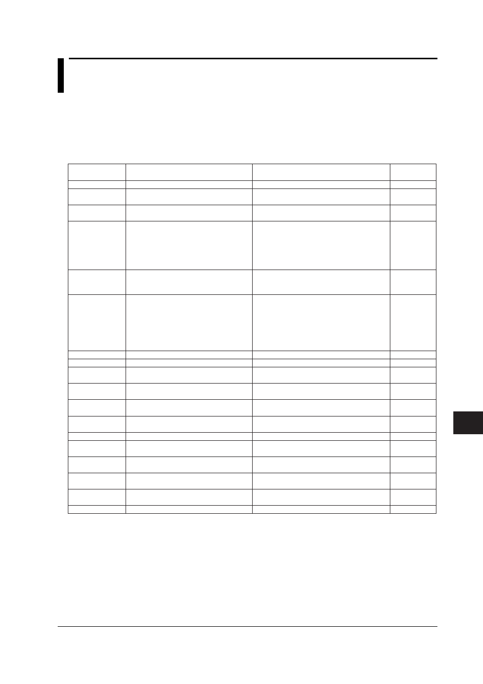
Register Assignments during Modbus Slave
The register assignments of the Modbus slave function are shown below. On the
CX1000, if you write to or read from a register that does not exist (communication
registers C13 to C30, measurement channels 07 to 20, computation channels 43 to 60,
and control loops 3 to 6), an error (error code 2) is returned.
• Hold Registers
40001-40030
40101
40301
40302
40303
40304
40305
40306
40501
40502
40503
40504
:
40577
40578
40579
40580
Communication register data
Control operation start/stop of all loops
Memory start/stop
Alarm ACK
Computation start/stop
Save the manual trigger, manual sampled,
snapshot, display data to the external
storage medium/saves the event data to
the external storage medium
Write message
Revert to the operation display
Alarm value of measurement channel 1
(Alarm number 1)
Alarm value of measurement channel 1
(Alarm number 2)
Alarm value of measurement channel 1
(Alarm number 3)
Alarm value of measurement channel 1
(Alarm number 4)
:
Alarm value of measurement channel 20
(Alarm number 1)
Alarm value of measurement channel 20
(Alarm number 2)
Alarm value of measurement channel 20
(Alarm number 3)
Alarm value of measurement channel 20
(Alarm number 4)
–32768 to 32767
0: Stop
1: Start
0: Memory stop
1: Memory start
When writing
0: Execute alarm ACK
When reading
0: Alarm not illuminated
1: Alarm illuminated
2: Alarm blinking
0: Stop computation
1: Start computation
2: Reset computation
0: Execute manual sampling
1: Activate manual trigger
2: Snapshot
3: Save display data to the external storage
medium
4: Save event data to the external storage
medium
1 to 8: Message number
0: Set the display back to the operation display
Value within the measurement span excluding
the decimal point (see the SA command)
Value within the measurement span excluding
the decimal point (see the SA command)
Value within the measurement span excluding
the decimal point (see the SA command)
Value within the measurement span excluding
the decimal point (see the SA command)
:
Value within the measurement span excluding
the decimal point (see the SA command)
Value within the measurement span excluding
the decimal point (see the SA command)
Value within the measurement span excluding
the decimal point (see the SA command)
Value within the measurement span excluding
the decimal point (see the SA command)
R/W
W
*1
R/W
R/W
R/W
W
*1
W
*1
W
*1
R/W
R/W
R/W
R/W
:
R/W
R/W
R/W
R/W
Modbus Register
Number
Description
Value
Read/Write
*1 If a write-only register in the hold registers is read, a “0” is returned.