Ascii output, Binary output, Ascii output -2 binary output -2 – Yokogawa Data Acquisition with PID Control CX2000 User Manual
Page 194
7-2
IM 04L31A01-17E
ASCII Output
The following types of ASCII data are available. For a description of the data formats,
see section 7.2.
Setting/basic setting data, decimal point position/unit information, measured/
computed/control data, SP number and PID number, control mode, program operation
mode, program pattern information that is currently in execution, PV event/time event
information, status of the program control end signal, communication log, FTP log,
operation error log, key login log, Web operation log, e-mail log, alarm summary,
message summary, status information, file list, data list, and user level
Syntax
EA
CRLF
...............
CRLF
:
...............
CRLF
...............
CRLF
EN
CRLF
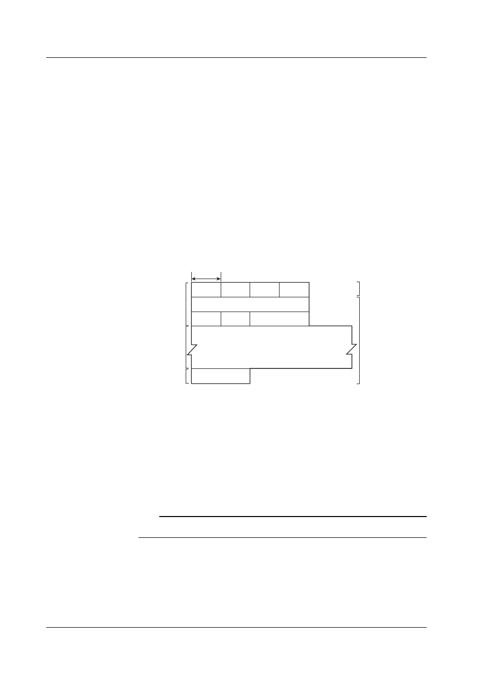
BINARY Output
Conceptual Diagram
'E'
'B'
BINARY Data
ASCII
BINARY
Data length
Data sum
Flag ID Header
sum
1 byte
BINARY header
(12 bytes)
BINARY data
BINARY data
(2 bytes)
CR
LF
EBCRLF
Indicates that the data is BINARY.
Data Length
The byte value of “flag + identifier + header sum + BINARY data + data sum.”
Header Sum
The sum value of “data length + flag + identifier.”
BINARY Data
For details on the output format of various data types, see section 7.3.
Data Sum
The sum value of “BINARY data.”
Note
The data length of the BINARY header section is output according to the byte order specified
with the BO command.
7.1 Response Syntax