Dc voltage measurement, Temperature measurement using an rtd, Temperature measurement when using a thermocouple – Yokogawa Touch Screen GP20 User Manual
Page 356: Rjc of tc input
5-2
IM 04L51B01-01EN
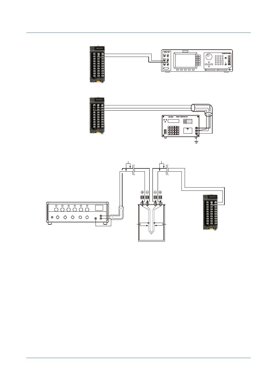
DC Voltage Measurement
CH1
Hi
Lo
DC voltage/current standard
Wiring to the first channel
of the module to calibrate
(Channel ��01)
+
–
Temperature Measurement Using an RTD
b
B
A
CH1
H
L
G
Resistance standard
The resistance of three
lead wires must be equal.
Wiring to the first channel
of the module to calibrate
(Channel ��01)
Temperature Measurement When Using a Thermocouple
+
–
+
−
CH1
Copper wires
Thermocouple wires or TC extension wires
Thermocouple
wires
Copper
wires
DC voltage standard
(0°C standard temperature device ZC-114/ZA-10 by Coper Electronics)
Uses the reference junction compensation
function of the GX/GP. See page 1-15
RJC of TC Input
As the measurement terminal of the GX/GP is generally at room temperature, the actual
output of the thermocouple is different from the values given on the thermoelectromotive
force table based on 0°C. The GX/GP performs compensation by measuring the
temperature at the input terminal and adding the corresponding thermoelectromotive force to
the actual output of the thermocouple. Therefore, when the measurement terminal is shorted
(equivalent to the case when the detector tip is 0°C), the measured value indicates the
temperature of the input terminal.
When calibrating the GX/GP, this compensation voltage (thermoelectromotive force of 0°C
reference corresponding to the input terminal temperature) must be subtracted from the
output of the standard generator before application. As shown in the figure, by using the 0°C
standard temperature device to compensate the reference junction at 0°C, you can input the
thermoelectromotive force of 0°C reference from the DC voltage standard and perform the
calibration.
5.1 Maintenance