Figure 3.8—using scanned data in logic 54 – Watlow Series D8 User Manual
Page 72
Chapter 3: Communicating by DeviceNet
Series D8 User’s Guide
54
Watlow Anafaze
Doc. 0600-3120-2000
tions from one PLC manufacturer to another, the same con-
cepts apply.
NOTE!
The contents of the scanner's M1 file cannot
be monitored directly in RSLogix™, the log-
ic-programming environment used in the fol-
lowing examples. For ease of demonstration
and troubleshooting, the relevant registers
are copied from the scanner's M1 file to the
PLC's N14 file.
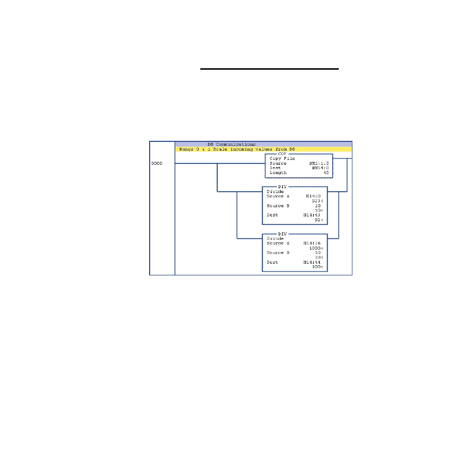
Figure 3.8
Using Scanned Data in Logic
For programming convenience the ladder program in
Figure 3.8 copies the portion of the scanner's memory to
which the D8's inputs are mapped into an integer file, N14:0.
This information is automatically polled so it does not require
special communication instructions to update values between
the D8 and the PLC. During every PLC scan the DeviceNet
scanner is queried for the latest values stored in its memory.
The D8 controller stores and communicates Process Variables
and other parameters in tenths of a degree (see Decimal Place-
ment for Numeric Values on page 59). In the logic a divide
function scales the scanned value into whole degrees. The
DIV function block divides the value in N14:0 (923) by 10
and places the temperature (92° F) into N14:43. This value can
be used elsewhere in logic, and the programmer will know
that the value is in degrees.