Figure 2.4—mounting bracket 15, Figure 2.4 mounting bracket – Watlow Series D8 User Manual
Page 33
Series D8 User’s Guide
Chapter 2: Installation
Doc. 0600-3120-2000
Watlow Anafaze
15
terminal blocks, and cables. The controller extends 188
mm (7.4 in.) behind the panel. Allow for an additional 41
to 54 mm (1.6 to 2.1 in.) beyond the connectors.
2. Temporarily cover any slots in the metal housing so that
dirt, metal filings, and pieces of wire do not enter the
housing and lodge in the electronics.
3. Cut a hole in the panel 46 mm (1.80 in.) by 92 mm (3.63
in.) as shown below. (This picture is NOT a template; it
is for illustration only.) Use caution; the dimensions giv-
en here have 1 mm (0.02 in.) tolerances.
4. Remove the brackets and collar from the controller, if
they are already in place.
5. Slide the controller into the panel cutout.
6. Slide the mounting collar over the back of the controller,
making sure the mounting screw indentations face to-
ward the back of the controller.
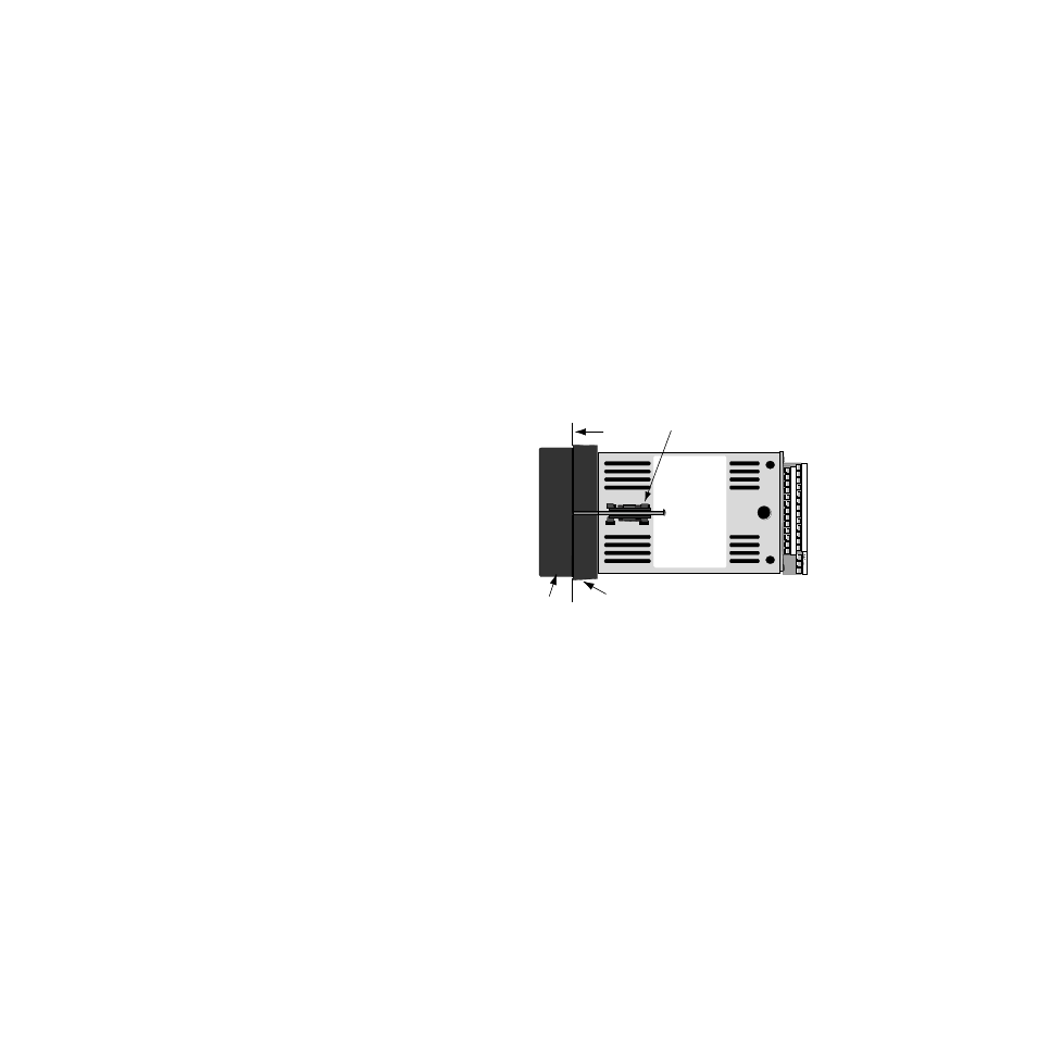
Figure 2.4
Mounting Bracket
7. Loosen the mounting bracket screws enough to allow for
the mounting collar and panel thickness. Place each
mounting bracket into the mounting slots (head of the
screw facing the back of the controller). Push each brack-
et backward then to the side to secure it to the controller
case.
8. Make sure the case is seated properly. Tighten the instal-
lation screws firmly against the mounting collar to secure
the unit. Ensure that the end of the mounting screws fit
into the indentations on the mounting collar.
+
2
4
6
8
10
12
14
16
18
20
22
24
26
1
3
5
7
9
11
13
15
17
19
21
23
25
Bracket (top and bottom)
Panel
Bezel
Mounting Collar