Replacing the flash memory chip, Replacing the flash memory chip 170 – Watlow Series D8 User Manual
Page 188
Chapter 7: Troubleshooting and Reconfiguring
Series D8 User’s Guide
170
Watlow Anafaze
Doc. 0600-3120-2000
Replacing the Flash Memory Chip
This procedure requires a 32-pin PLCC IC extraction tool.
CAUTION!
The flash memory chip and other compo-
nents are sensitive to damage from electro-
static discharge (ESD). To prevent ESD
damage, use an ESD wrist strap or other an-
tistatic device.
NOTE!
Replacing the flash memory chip results in
full erasure of RAM. Make a record of all pa-
rameters before changing the flash memory
chip.
1. Make a record of controller parameters.
2. Switch off power to the controller.
3. Disconnect input power to the controller.
4. Remove the four screws from the sides of the controller
front bezel.
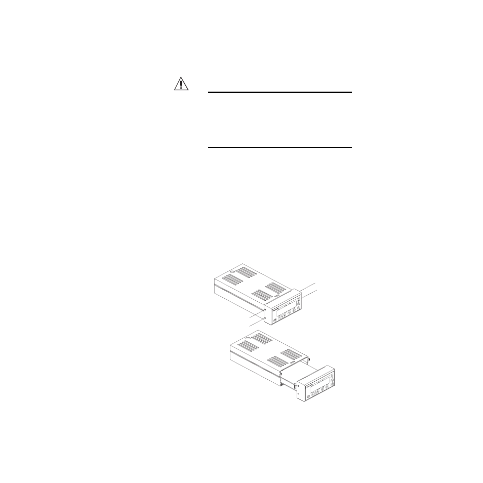
5. Remove the electronics assembly from the case, as
Figure 7.1
Removal of Electronics Assembly
from Case
D8
D8
- 12LS Controller (111 pages)
- 8LS Controller (140 pages)
- 8PID Controller (55 pages)
- Addendum to EZwarePlus (50 pages)
- ANASCAN (62 pages)
- ANASOFT (95 pages)
- ANAWIN 2 (154 pages)
- ANAWIN 3 (23 pages)
- Calibrating Watlow Series 988 Family Process Controls (19 pages)
- CAS (98 pages)
- CAS200 (124 pages)
- CLS (180 pages)
- CLS200 (251 pages)
- CLS200, MLS300 and CAS200 (92 pages)
- Control Console (12 pages)
- CPC400 (230 pages)
- DIN-A-MITE Style A (9 pages)
- DIN-A-MITE Style B (14 pages)
- DIN-A-MITE Style C (22 pages)
- DIN-A-MITE Style D (9 pages)
- DIN-Mount Adapter Instruction Sheet, Rev A (1 page)
- Dual DAC (4 pages)
- EM Gateway (28 pages)
- E-Safe Hybrid Relay Rev B (4 pages)
- E-SAFE II Hybrid Power Switch (4 pages)
- EZwarePlus Programming (264 pages)
- EZ-ZONE PM (111 pages)
- EZ-ZONE PM PID (125 pages)
- EZ-ZONE PM Express Limit (34 pages)
- EZ-ZONE PM Express (35 pages)
- EZ-ZONE PM Integrated Controller (181 pages)
- EZ-ZONE RM Limit Module Rev C (127 pages)
- EZ-ZONE RMA Modul (79 pages)
- EZ-ZONE RMC (236 pages)
- EZ-ZONE RME (124 pages)
- EZ-ZONE RMH (161 pages)
- EZ-ZONE RUI/Gateway (62 pages)
- EZ-ZONE RM-Scanner-Modul (140 pages)
- EZ-ZONE ST (97 pages)
- F4 External Event Board - Rev.B (2 pages)
- HG Series Mercury Displacement Relay (6 pages)
- LogicPro (296 pages)
- Mercury Relay or MDR Retrofit (13 pages)
- MICRODIN (24 pages)
- MICRODIN (106 pages)