Current inputs, Current inputs 173, Figure 7.4—input circuit 173 – Watlow Series D8 User Manual
Page 191: Table 7.5—resistor values for current inputs 173
Series D8 User’s Guide
Chapter 7: Troubleshooting and Reconfiguring
Doc. 0600-3120-2000
Watlow Anafaze
173
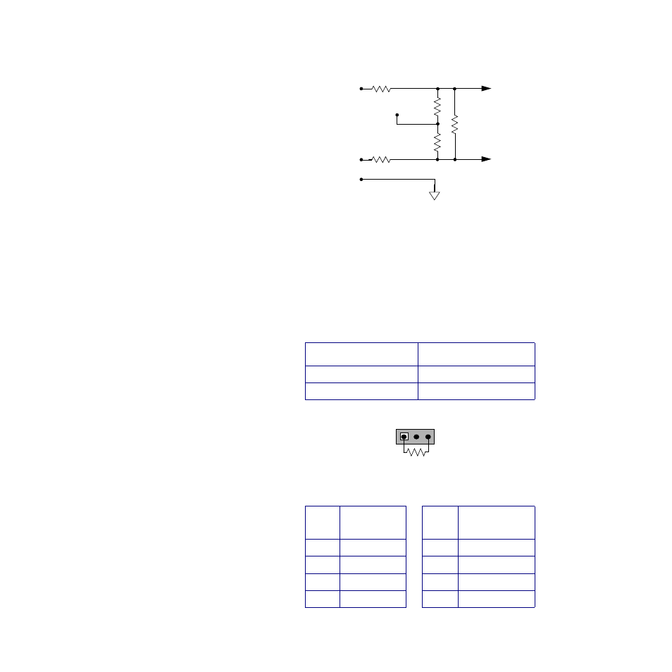
Figure 7.4
Input Circuit
Current Inputs
For each current input, you must install a resistor. The value
of the resistor must be correct for the expected input range. In-
stall the resistor in the listed resistor pack (RP) location. Note
the resistor pack locations have three through-holes. Install
the resistor as shown in the illustration below.
Table 7.5
Resistor Values for Current Inputs
Resistor tolerance:
±
0.1%
Table 7.6
Resistor Locations for Current In-
puts
Input Range
Resistor Value RD
0 to 10 mA
6.0
Ω
0 to 20 mA
3.0
Ω
Loop
Resistor
Location RD
Loop
Resistor
Location RD
1
RP1
5
RP5
2
RP2
6
RP6
3
RP3
7
RP7
4
RP4
8
RP8
Com
IN-
RC (RTD)
IN+
RD
RP
Analog
Input
Terminal
Internal
RP
+5 Vdc
Reference
To D8
Circuitry
RC (Voltage)
+
-
RP#
RD
- 12LS Controller (111 pages)
- 8LS Controller (140 pages)
- 8PID Controller (55 pages)
- Addendum to EZwarePlus (50 pages)
- ANASCAN (62 pages)
- ANASOFT (95 pages)
- ANAWIN 2 (154 pages)
- ANAWIN 3 (23 pages)
- Calibrating Watlow Series 988 Family Process Controls (19 pages)
- CAS (98 pages)
- CAS200 (124 pages)
- CLS (180 pages)
- CLS200 (251 pages)
- CLS200, MLS300 and CAS200 (92 pages)
- Control Console (12 pages)
- CPC400 (230 pages)
- DIN-A-MITE Style A (9 pages)
- DIN-A-MITE Style B (14 pages)
- DIN-A-MITE Style C (22 pages)
- DIN-A-MITE Style D (9 pages)
- DIN-Mount Adapter Instruction Sheet, Rev A (1 page)
- Dual DAC (4 pages)
- EM Gateway (28 pages)
- E-Safe Hybrid Relay Rev B (4 pages)
- E-SAFE II Hybrid Power Switch (4 pages)
- EZwarePlus Programming (264 pages)
- EZ-ZONE PM (111 pages)
- EZ-ZONE PM PID (125 pages)
- EZ-ZONE PM Express Limit (34 pages)
- EZ-ZONE PM Express (35 pages)
- EZ-ZONE PM Integrated Controller (181 pages)
- EZ-ZONE RM Limit Module Rev C (127 pages)
- EZ-ZONE RMA Modul (79 pages)
- EZ-ZONE RMC (236 pages)
- EZ-ZONE RME (124 pages)
- EZ-ZONE RMH (161 pages)
- EZ-ZONE RUI/Gateway (62 pages)
- EZ-ZONE RM-Scanner-Modul (140 pages)
- EZ-ZONE ST (97 pages)
- F4 External Event Board - Rev.B (2 pages)
- HG Series Mercury Displacement Relay (6 pages)
- LogicPro (296 pages)
- Mercury Relay or MDR Retrofit (13 pages)
- MICRODIN (24 pages)
- MICRODIN (106 pages)