Digital inputs, Digital inputs 35, Figure 2.22—wiring digital inputs 35 – Watlow Series D8 User Manual
Page 53
Series D8 User’s Guide
Chapter 2: Installation
Doc. 0600-3120-2000
Watlow Anafaze
35
Digital Inputs
All digital inputs are transistor-transistor logic (TTL) level in-
puts referenced to controller common and the internal +5 V
power supply of the D8.
When an input is connected to the controller common, the in-
put is considered on. Otherwise, the input is considered off.
Most features that use the digital inputs can be user-config-
ured to activate when an input is either on or off.
In the off state, internal 4.7 k
Ω
resistors pull the digital inputs
high to 5 Vdc with respect to the controller common.
Table 2.5
Digital Input States and Values
Stored in the Controller
1
Read and write these values through communications.
External Switching Device
To ensure that the inputs are reliably switched, use a switching
device with the appropriate impedances in the on and off
states and do not connect the inputs to external power sources.
When open, the switching device must provide an impedance
of at least 14 k
Ω
to ensure that the voltage will rise to greater
than 3.7 Vdc. When closed, the switch must provide not more
than 1.7 k
Ω
impedance to ensure the voltage drops below 1.3
Vdc.
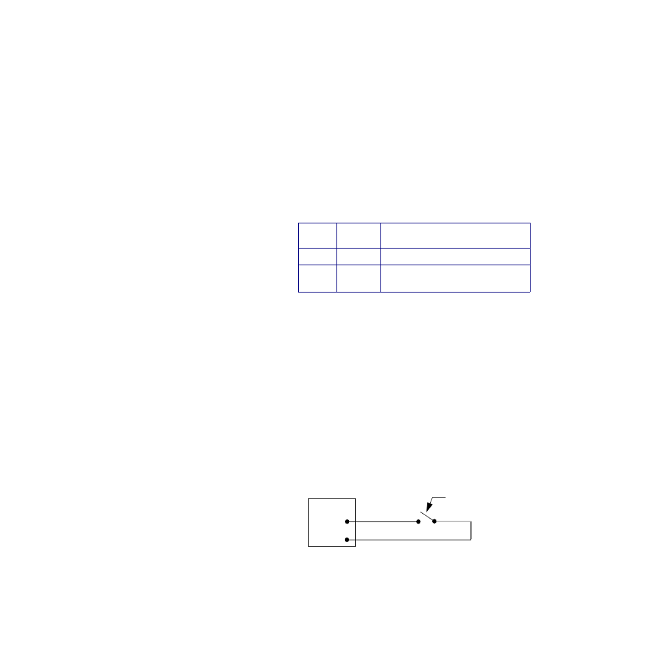
To install a switch as a digital input, connect one lead to the
common terminal on the TB50 (terminals 3 and 4) or TB18
(terminal 2). Connect the other lead to the desired digital input
terminal on the TB50 (terminals 43 to 50) or TB18 (terminals
16 to 18).
Figure 2.22 Wiring Digital Inputs
State
Value
1
Description
Off
0
Open circuit
On
1
Digital input connected to controller
common
External
Switching
Device
TB50
Input
Control Com