Assigning plc addresses, Assigning plc addresses 51, Figure 3.5—adding the d8 to the scanlist 51 – Watlow Series D8 User Manual
Page 69
Series D8 User’s Guide
Chapter 3: Communicating by DeviceNet
Doc. 0600-3120-2000
Watlow Anafaze
51
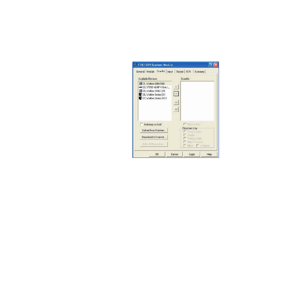
device starting at the next available byte in the PLC
memory. When not checked the user controls how the
bytes are arranged.)
3. Select 01 Watlow D84/D88 by clicking it in the Available
Devices
list.
4. Click the right-arrow button to put the D8 on the Scanlist.
Figure 3.5
Adding the D8 to the Scanlist
Assigning PLC Addresses
Once the device has been added to the Scanlist, it is possible
to map the polled bytes to any available contiguous memory
location for both inputs and outputs.
The Allen-Bradley 1747-SDN scanner module in this exam-
ple consumes the first 32 words of the input and output files
corresponding to the slot in which it is inserted. For example,
when the module is inserted in slot 3 of the PLC, the scanner
uses addresses in the input file I:3.0 through I:3.31. This pro-
vides only 32 words of memory. Because the D88 controller
supplies 81 bytes or 40.5 words of input, it is necessary to map
the incoming polled data to the scanner's M1 file instead.
The following procedure maps the D88's input bytes to the
scanner's M1 file. Actually only 40 words or 80 bytes of input
data will be mapped because the Exception Status Byte, which
is currently unused, is excluded.