Thermocouple connections, Thermocouple connections 29, Figure 2.13—thermocouple connections 29 – Watlow Series D8 User Manual
Page 47
Series D8 User’s Guide
Chapter 2: Installation
Doc. 0600-3120-2000
Watlow Anafaze
29
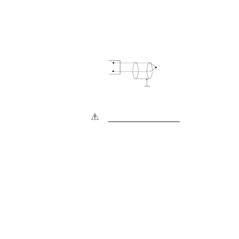
Thermocouple Connections
Connect the positive lead of the thermocouple to the IN+ ter-
minal for one of the loops, and connect the negative lead to the
corresponding IN- terminal.
Use 18 or 20 AWG (0.5 or 0.75 mm
2
) for all thermocouple in-
puts. Most thermocouple wire is solid, unshielded wire. When
using shielded wire, ground one end only.
Figure 2.13 Thermocouple Connections
CAUTION!
Ground loops and common mode noise can
damage the controller or disrupt measure-
ments. To minimize ground loops and com-
mon mode noise:
• Do not mix grounded and ungrounded ther-
mocouples. If any thermocouple connected
to the controller is of grounded construction,
all thermocouples should be of grounded
construction and each should be connected
to ground at the process end.
• Connect the earth ground terminal on TB2
to a good earth ground, but do not connect
the analog common to earth ground. The D8
uses a floating analog common for sensor
measurements. The noise protection circuits
on the sensor inputs function correctly only
if the controller is correctly installed. See
Ground Loops on page 22.
White
Red
Type J thermocouple
CH IN+
CH IN-
Shield (if present)
Earth Ground at Process End