Mac id, Baud rate, Module led – Watlow Series D8 User Manual
Page 148: Network led, Bus off count, Mac id 130, Baud rate 130, Module led 130, Network led 130, Bus off count 130
Chapter 6: Menu and Parameter Reference
Series D8 User’s Guide
130
Watlow Anafaze
Doc. 0600-3120-2000
Table 6.6
Digital Output Alarm Polarity
MAC ID
The node address for the controller. This value is set with the
Address rotary switches. See Connecting the D8 to a De-
Values
: 00 to 63
DeviceNet Object
: DeviceNet (03 hex)
Baud Rate
Indicates the baud rate for communications. This value is set
with the Data Rate rotary switch. See Connecting the D8 to a
Values
: 125, 250, 500K
DeviceNet Object
: DeviceNet (03 hex)
Module LED
Indicates the status of the Module LED
Values
: off, green, red, flashing red, flashing green ( see Mod-
ule Status Indicator Light on page 44).
DeviceNet Object
: N/A
Network LED
Indicates the status of the Network LED
Values:
off, flashing green, green, flashing red, red, (see Net-
work Status Indicator Light on page 44).
DeviceNet Object:
N/A
Bus Off Count
Indicates the number of times the controller has gone to the
bus-off state.
Values
: 0 (indicates the controller has not had a bus off error
since the last power cycle) or 1 (indicates the controller has
gone bus off since the last power cycle)
DeviceNet Object
: DeviceNet (03 hex)
Display Value
DeviceNet Value
Description
on
0
Digital alarm outputs sink current to analog common
when an alarm occurs.
off
1
Digital alarm outputs stop sinking current to analog com-
mon when an alarm occurs.
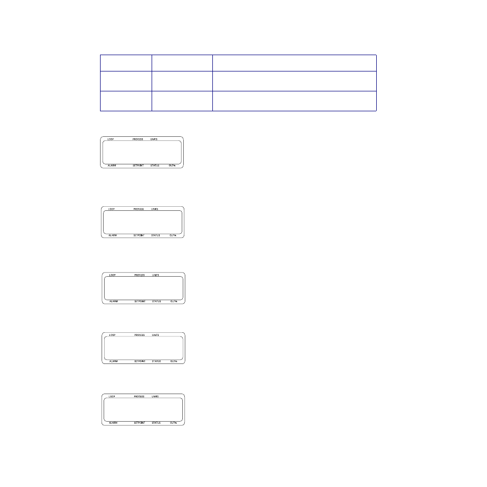
lMAC ID r
b63
lBaud rate r
b500
l
lNetwork LED r
green
lBus off count r
0