Figure 2.20—tb50 watchdog timer output 34, Figure 2.21—tb18 watchdog timer output 34 – Watlow Series D8 User Manual
Page 52
Chapter 2: Installation
Series D8 User’s Guide
34
Watlow Anafaze
Doc. 0600-3120-2000
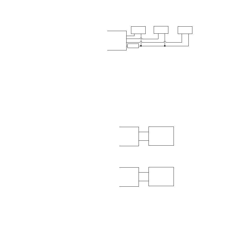
Figure 2.19 Output Connections Using
External Power Supply
CPU Watchdog Timer
The CPU watchdog timer constantly monitors the micropro-
cessor. It is a sink output located on TB50 terminal 6 or TB18
terminal 3. The output can be connected to an external circuit
or device to monitor whether the controller is powered and op-
erational. The output is on (low) when the microprocessor is
operating; when it stops operating, the output goes off (high).
Figure 2.20 and Figure 2.21 show the recommended circuit
for the watchdog timer output for the TB50 and the TB18.
Figure 2.20 TB50 Watchdog Timer Output
Figure 2.21 TB18 Watchdog Timer Output
Heat Output
Cool Output
Alarm Output
Common
+
-
SSR
TB50 or TB18
- PS +
+
-
SSR
+
-
SSR
SSR
+ 5 Vdc
Watchdog Timer
(Terminal 1)
(Terminal 6)
TB50
+
-
SSR
+ 5 Vdc
Watchdog Timer
(Terminal 1)
(Terminal 3)
TB18
+
-
- 12LS Controller (111 pages)
- 8LS Controller (140 pages)
- 8PID Controller (55 pages)
- Addendum to EZwarePlus (50 pages)
- ANASCAN (62 pages)
- ANASOFT (95 pages)
- ANAWIN 2 (154 pages)
- ANAWIN 3 (23 pages)
- Calibrating Watlow Series 988 Family Process Controls (19 pages)
- CAS (98 pages)
- CAS200 (124 pages)
- CLS (180 pages)
- CLS200 (251 pages)
- CLS200, MLS300 and CAS200 (92 pages)
- Control Console (12 pages)
- CPC400 (230 pages)
- DIN-A-MITE Style A (9 pages)
- DIN-A-MITE Style B (14 pages)
- DIN-A-MITE Style C (22 pages)
- DIN-A-MITE Style D (9 pages)
- DIN-Mount Adapter Instruction Sheet, Rev A (1 page)
- Dual DAC (4 pages)
- EM Gateway (28 pages)
- E-Safe Hybrid Relay Rev B (4 pages)
- E-SAFE II Hybrid Power Switch (4 pages)
- EZwarePlus Programming (264 pages)
- EZ-ZONE PM (111 pages)
- EZ-ZONE PM PID (125 pages)
- EZ-ZONE PM Express Limit (34 pages)
- EZ-ZONE PM Express (35 pages)
- EZ-ZONE PM Integrated Controller (181 pages)
- EZ-ZONE RM Limit Module Rev C (127 pages)
- EZ-ZONE RMA Modul (79 pages)
- EZ-ZONE RMC (236 pages)
- EZ-ZONE RME (124 pages)
- EZ-ZONE RMH (161 pages)
- EZ-ZONE RUI/Gateway (62 pages)
- EZ-ZONE RM-Scanner-Modul (140 pages)
- EZ-ZONE ST (97 pages)
- F4 External Event Board - Rev.B (2 pages)
- HG Series Mercury Displacement Relay (6 pages)
- LogicPro (296 pages)
- Mercury Relay or MDR Retrofit (13 pages)
- MICRODIN (106 pages)
- MICRODIN (24 pages)