Watlow Series D8 User Manual
Page 51
Series D8 User’s Guide
Chapter 2: Installation
Doc. 0600-3120-2000
Watlow Anafaze
33
Configuring Outputs
As you choose outputs for control and alarms, bear in mind
the following points:
•
You can enable or disable the control outputs. By default,
heat outputs are enabled and cool outputs are disabled.
•
You can program each control output individually for on/
off, time proportioning, distributed zero-crossing or Se-
rial DAC control.
•
You can individually program each control output for di-
rect or reverse action.
•
Alarm outputs other than the global alarm are non-latch-
ing. See Global Alarm on page 97.
•
Alarms can be suppressed during process start up and for
preprogrammed durations. See Power Up Alarm Delay
•
Alarm outputs can be configured, as a group, to sink to
output during an alarm or stop current flow during an
alarm. See Digital Output Alarm Polarity on page 129.
Control and Alarm Output Connections
Typically control and alarm outputs use external optically-
isolated solid state relays (SSRs). SSRs accept a 3 to 32 Vdc
input for control, and some can switch up to 100 Amps at 480
Vac. For larger currents, use silicon control rectifier (SCR)
power controllers up to 1000 Amps at 120 to 600 Vac. You
can also use SCRs and a Serial DAC for phase-angle fired
control.
The control and alarm outputs are open collector outputs ref-
erenced in the D8’s common. Each output sinks up to 60
mAdc to the controller common when on.
NOTE!
Control outputs are sink outputs. They sink
current when the output is on. Connect them
to the negative side of solid state relays.
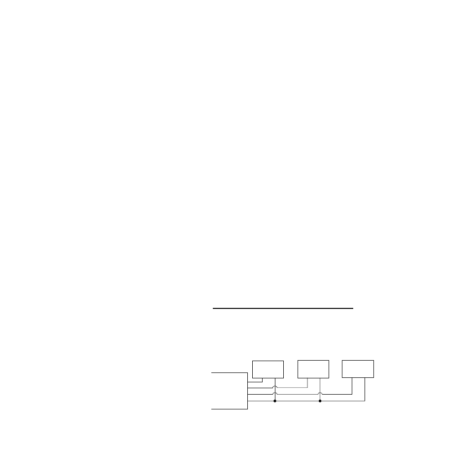
Figure 2.18 shows sample heat, cool and alarm output connec-
tions.
Figure 2.18 Sample Heat, Cool and Alarm
Output Connections
Heat Output
Cool Output
Alarm Output
+5 Vdc
+
-
+
-
+
-
SSR
SSR
SSR
TB50 or TB18