Technical description, Technical description 6, D8 6 – Watlow Series D8 User Manual
Page 24: Figure 1.2—d8 special inputs parts list 6, Figure 1.3—d8 rear views 6, D8si
Chapter 1: System Overview
Series D8 User’s Guide
6
Watlow Anafaze
Doc. 0600-3120-2000
Figure 1.2
D8 Special Inputs Parts List
Technical Description
This section contains a technical description of each compo-
nent of the D8 series controller.
D8
The D8 is housed in a 1/8-DIN panel mount package. It con-
tains the central processing unit (CPU), random access mem-
ory (RAM) with a built-in battery, flash memory, communi-
cations, digital I/O, analog inputs, display and touch keypad.
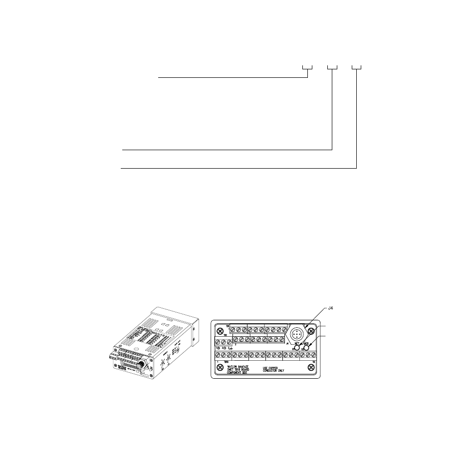
Figure 1.3
D8 Rear Views
D8SI _ _ - _ _ - _ _
Special/Process Input Type
(Not required for thermocouple sensor inputs)
23 = RTD
43 = 0 to 10 mA dc
44 = 0 to 20 mA dc or 4 to 20 mA dc
50 = 0 to 100 mV dc
52 = 0 to 500 mV dc
53 = 0 to 1 Vdc
55 = 0 to 5 Vdc
56 = 0 to 10 Vdc
57 = 0 to 12 Vdc
Start Loop
XX = Loop number XX
End Loop
XX = Loop number XX
DeviceNet
Connector
Network LED
Indicator Light
Module LED
Indicator Light
Series D8 with SCSI Connector.
Series D8 with TB18 Connector.