Reversed thermocouple detection, Display format, Reversed thermocouple detection 133 – Watlow Series D8 User Manual
Page 151: Display format 133, Table 6.9—calibration offset ranges 133
Series D8 User’s Guide
Chapter 6: Menu and Parameter Reference
Doc. 0600-3120-2000
Watlow Anafaze
133
Decimal Placement for DeviceNet:
for Numeric Values on page 59.
DeviceNet Object
: Input (64 hex)
Table 6.9
Calibration Offset Ranges
Reversed Thermocouple Detection
Choose whether to enable polarity checking for thermocou-
ples. If the controller detects a reversed thermocouple, it acti-
vates an alarm and sets the loop to manual mode at the power
level indicated by the Sensor fail heat output or Sensor fail
cool output
parameter in the Output menu.
Values:
on (1) or off (0). Values in parentheses are for com-
munications.
Default:
on (1)
DeviceNet Object:
Input (64 hex)
Display Format
For a process input, choose the range and the number of dec-
imal places for the process variable and related parameters.
Choose a precision appropriate for the range and accuracy of
the sensor.
Values:
Default:
-999 to 3000 for a process input.
DeviceNet Object
: Input (64 hex)
Type of Sensor
Offset Range
˚F
˚C
RTD
-300.0 to 300.0
-300.0 to 300.0
J Thermocouple
K Thermocouple
T Thermocouple
-300 to 300
-300 to 300
B Thermocouple
S Thermocouple
-300 to 76
-300 to 300
R Thermocouple
-300 to 66
-300 to 300
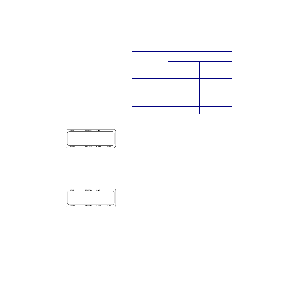
l01 Reversed r
T/C detect b on
l01 Disp formatr
b -999to 3000