Sample ladder logic, Accessing polled i/o data, Sample ladder logic 53 – Watlow Series D8 User Manual
Page 71: Accessing polled i/o data 53, Figure 3.7—advanced mapping dialog box 53
Series D8 User’s Guide
Chapter 3: Communicating by DeviceNet
Doc. 0600-3120-2000
Watlow Anafaze
53
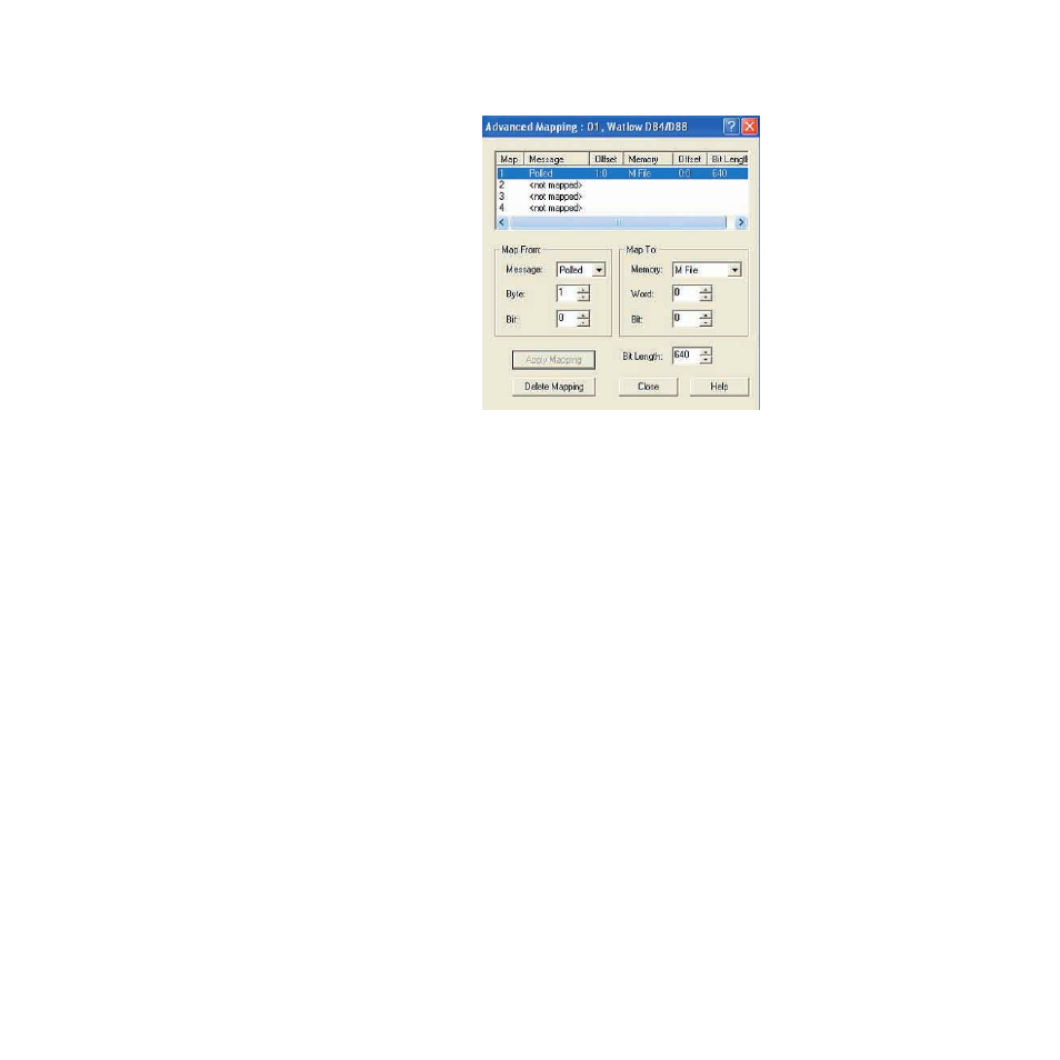
Figure 3.7
Advanced Mapping Dialog Box
The D8's polled input data is now mapped to the scanner's M1
file.
The scanner's M0 file may similarly be used to map the De-
viceNet output data. The output data is easier to map because
there is no Exception Status Byte to omit. See Poll Connection
on page 64 for information on the output data.
Sample Ladder Logic
The following sections give examples of using information
from the polled I/O and using explicit messages to read and
write data between the D8 controller and a PLC.
Accessing Polled I/O Data
For a better understanding of the ladder logic examples in this
section, refer to Figure 3.14 and Figure 3.15 starting on page
65. These figures illustrate the polled input and output mes-
sages. Because the first byte of the input data, the Exception
Status Byte was excluded, the first word mapped is loop 1's
Process Variable, and it is stored in the scanner's memory at
M1:1.0. The Process Variables for subsequent loops are in the
next seven memory locations (M1:1.1 to M1:1.7).
All ladder logic examples that follow were made using an
Allen-Bradley SLC 5/04. Although there are different instruc-