Table 8.14—digital outputs control / alarm 188, Table 8.16—communications 188, Table 8.17—d8 power requirements 188 – Watlow Series D8 User Manual
Page 206
Chapter 8: Specifications
Series D8 User’s Guide
188
Watlow Anafaze
Doc. 0600-3120-2000
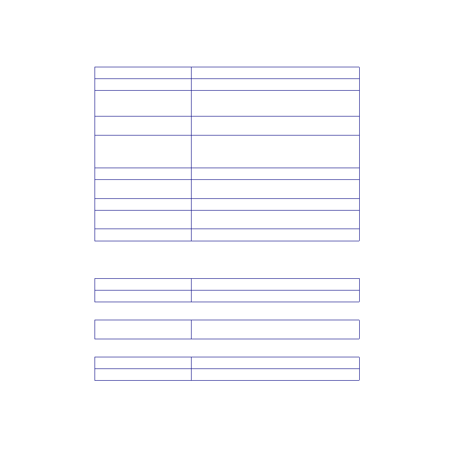
Digital Outputs
Table 8.14
Digital Outputs Control / Alarm
Table 8.15
5 Vdc Output (Power to Operate
Solid-State Relays)
Table 8.16
Communications
Table 8.17
D8 Power Requirements
Number
20 with TB50 option or 13 with TB18 option
Operation
Open collector output; ON state sinks to logic common
Function
1 Global alarm output
1 CPU watchdog output
Balance selectable as closed-loop control or alarms
Number of Control Outputs per
PID Loop
2 (maximum)
Control Output Types
Time proportioning, distributed zero crossing, Serial DAC or
on/off. All independently selectable for each output. Heat and
cool control outputs can be individually disabled for use as
alarm outputs
Time Proportioning Cycle Time
1 to 255 seconds, programmable for each output
Control Action
Reverse (heat) or direct (cool), independently selectable for
each output
Off State Leakage Current
<0.01 mA to dc common
Maximum Current
60 mA for each output. 5V power supply (from the processor
module) can supply up to 350 mA total to all outputs
Maximum Voltage Switched
24 Vdc
Voltage
5 Vdc
Maximum Current
350 mA
Minimum Time Between
Polled I/O Requests
20 ms
Voltage
15 to 24 +/-3 Vdc
Maximum Current
1 A