Figure 7.2—screw locations on pc board 171, Figure 7.3—location of flash memory chip 171 – Watlow Series D8 User Manual
Page 189
Series D8 User’s Guide
Chapter 7: Troubleshooting and Reconfiguring
Doc. 0600-3120-2000
Watlow Anafaze
171
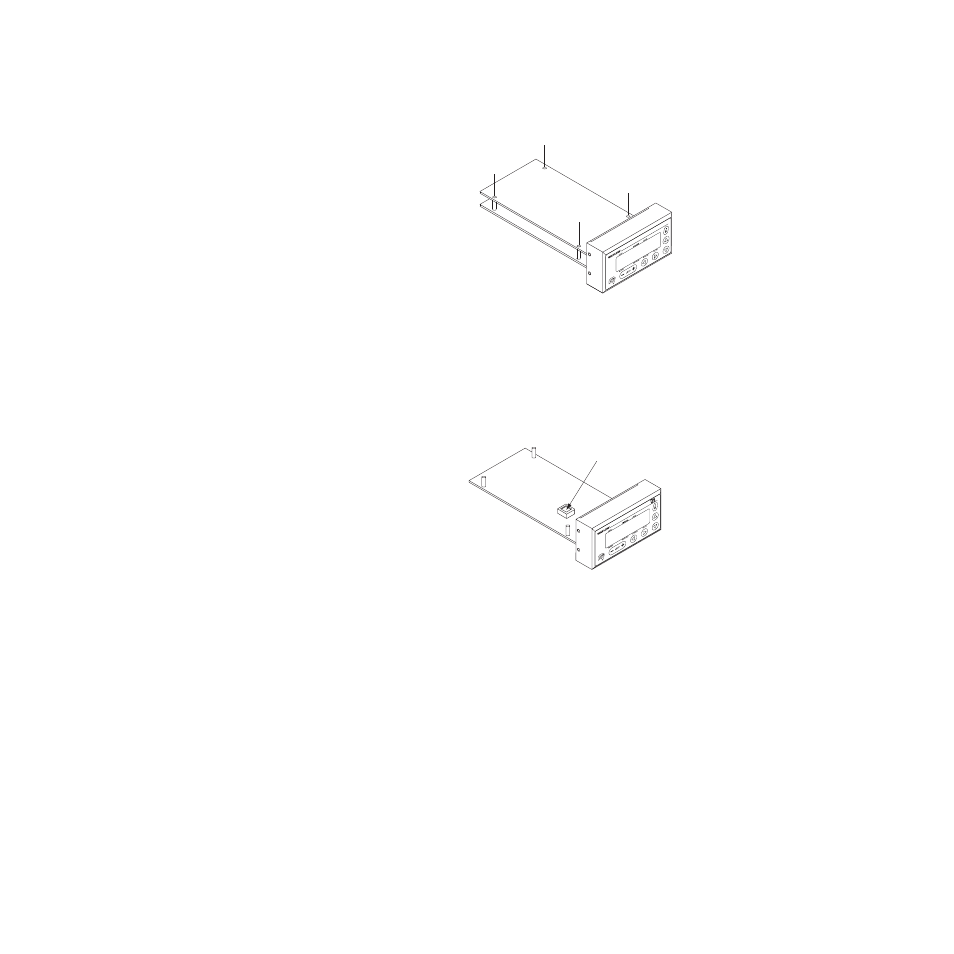
6. Unscrew the four screws at the corners of the top board
and carefully unplug this board to access the bottom
board. Figure 7.2 shows the screws to remove:
Figure 7.2
Screw Locations on PC Board
7. Locate the flash memory chip on the circuit board. The
flash memory chip is a 32-pin socketed chip that is la-
beled with the model, version and checksum.
Figure 7.3
Location of Flash Memory Chip
8. Remove the existing flash memory chip from its socket
with an IC extraction tool.
9. Carefully insert the new flash memory chip into the sock-
et. Make sure that the chip is oriented so that its notch fits
in the corresponding corner of the socket.
10. Reverse steps 2 through 6 to reassemble the unit.
11. Power up the controller.
12. Re-enter parameters.
D8
- 12LS Controller (111 pages)
- 8LS Controller (140 pages)
- 8PID Controller (55 pages)
- Addendum to EZwarePlus (50 pages)
- ANASCAN (62 pages)
- ANASOFT (95 pages)
- ANAWIN 2 (154 pages)
- ANAWIN 3 (23 pages)
- Calibrating Watlow Series 988 Family Process Controls (19 pages)
- CAS (98 pages)
- CAS200 (124 pages)
- CLS (180 pages)
- CLS200 (251 pages)
- CLS200, MLS300 and CAS200 (92 pages)
- Control Console (12 pages)
- CPC400 (230 pages)
- DIN-A-MITE Style A (9 pages)
- DIN-A-MITE Style B (14 pages)
- DIN-A-MITE Style C (22 pages)
- DIN-A-MITE Style D (9 pages)
- DIN-Mount Adapter Instruction Sheet, Rev A (1 page)
- Dual DAC (4 pages)
- EM Gateway (28 pages)
- E-Safe Hybrid Relay Rev B (4 pages)
- E-SAFE II Hybrid Power Switch (4 pages)
- EZwarePlus Programming (264 pages)
- EZ-ZONE PM (111 pages)
- EZ-ZONE PM PID (125 pages)
- EZ-ZONE PM Express Limit (34 pages)
- EZ-ZONE PM Express (35 pages)
- EZ-ZONE PM Integrated Controller (181 pages)
- EZ-ZONE RM Limit Module Rev C (127 pages)
- EZ-ZONE RMA Modul (79 pages)
- EZ-ZONE RMC (236 pages)
- EZ-ZONE RME (124 pages)
- EZ-ZONE RMH (161 pages)
- EZ-ZONE RUI/Gateway (62 pages)
- EZ-ZONE RM-Scanner-Modul (140 pages)
- EZ-ZONE ST (97 pages)
- F4 External Event Board - Rev.B (2 pages)
- HG Series Mercury Displacement Relay (6 pages)
- LogicPro (296 pages)
- Mercury Relay or MDR Retrofit (13 pages)
- MICRODIN (24 pages)
- MICRODIN (106 pages)