Rtd input connections, Voltage input connections, Current input connections – Watlow Series D8 User Manual
Page 48: Rtd input connections 30, Voltage input connections 30, Current input connections 30, Figure 2.14—rtd connections 30, Figure 2.15—voltage signal connections 30, Figure 2.16—current signal connections 30
Chapter 2: Installation
Series D8 User’s Guide
30
Watlow Anafaze
Doc. 0600-3120-2000
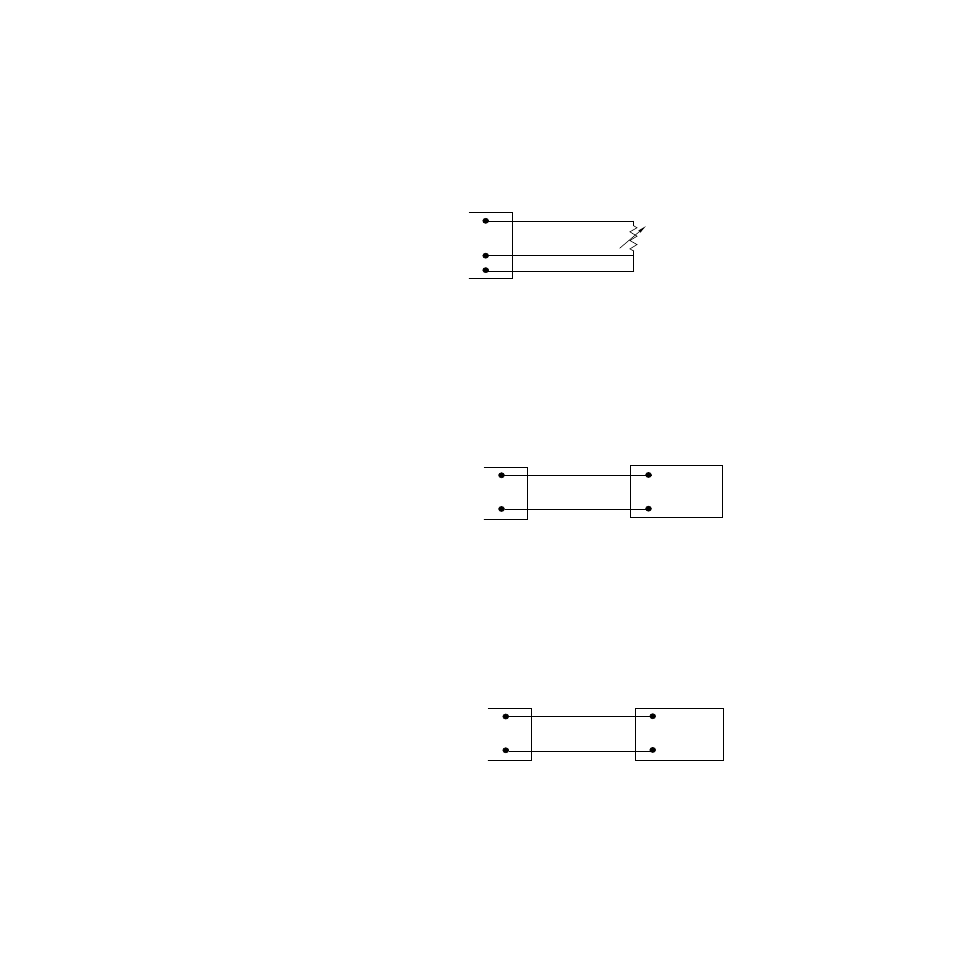
RTD Input Connections
RTD inputs require accessory resistors. Watlow Anafaze rec-
ommends that you use a 100
Ω
, three-wire platinum RTD to
prevent reading errors due to cable resistance. If you use a
two-wire RTD, jumper the negative input to common. If you
must use a four-wire RTD, leave the fourth wire unconnected.
Figure 2.14 RTD Connections
Voltage Input Connections
Voltage inputs with ranges greater than -10 to 60 mV require
accessory resistors. Special input resistors installed at Watlow
Anafaze divide analog input voltages such that the controller
sees a -10 to 60 mV signal on the loop.
Figure 2.15 Voltage Signal Connections
Current Input Connections
Current inputs require accessory resistors. Special input resis-
tors installed at Watlow Anafaze for analog current signals are
such that the controller sees a -10 to 60 mV signal across its
inputs for the loop.
Figure 2.16 Current Signal Connections
100
Ω
RTD
IN +
IN -
Com
CH
CH
CH IN+
CH IN-
Device with
Output
Voltage
CH IN+
CH IN-
Device with
Current
Output