Status indicators, Status indicators 43, Figure 2.29—d8 side with rotary switches 43 – Watlow Series D8 User Manual
Page 61
Series D8 User’s Guide
Chapter 2: Installation
Doc. 0600-3120-2000
Watlow Anafaze
43
selection, the controller will always come back up on the net-
work with the last software configured node address stored in
the controller's memory.
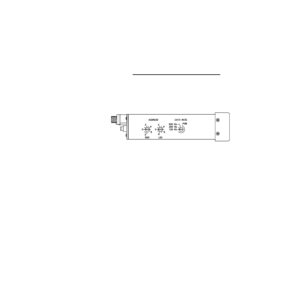
Set the controller’s MAC ID with the two rotary switches on
the side of the case. Set the most significant digit (MSD) with
the left switch and the least significant digit (LSD) with the
right switch. For example, to set the address to 23, set the
MSD to 2 and the LSD to 3.
NOTE!
If the node address is changed with the
switch, the D8 controller’s power must be cy-
cled before the change takes effect. If the
node address is changed using software, the
change takes effect immediately.
Figure 2.29 D8 Side with Rotary Switches
Status Indicators
The D8 controller has two indicator lights on the back, one la-
beled “NET” (Network) and the other labeled “MOD” (Mod-
ule). On power-up the controller performs a self-test. The
indicator light identified as "MOD" displays the result of this
test as either pass (green) or fail (red). Also, under normal op-
eration the indicator lights indicate the health of the module
and the network. In the event that an indicator light should go
from green to red either on power up or afterwards, consult ta-
bles Table 2.10 and Table 2.11 below for basic troubleshoot-
ing.