Typical installation, Mounting controller components, Typical installation 12 – Watlow Series D8 User Manual
Page 30: Mounting controller components 12, Figure 2.1—d8 system components 12
Chapter 2: Installation
Series D8 User’s Guide
12
Watlow Anafaze
Doc. 0600-3120-2000
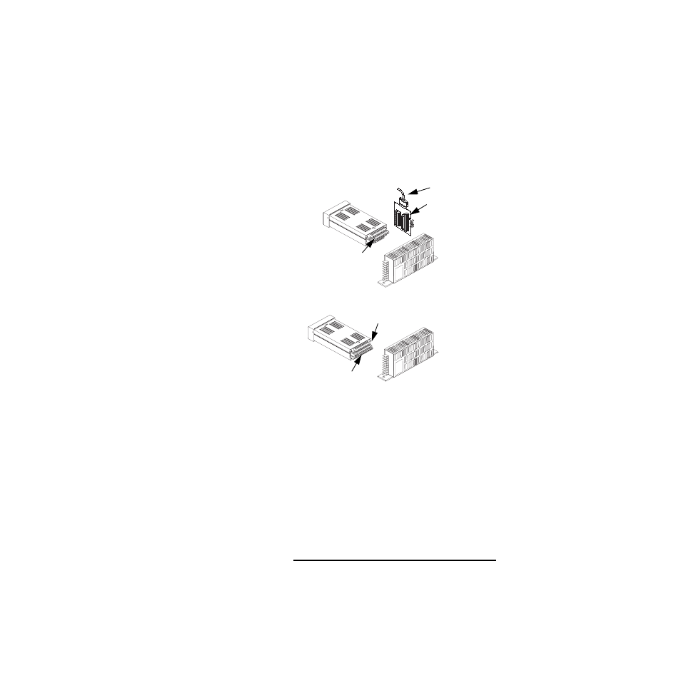
Typical Installation
Figure 2.1 shows typical installations of the controller with
the TB50 and the TB18 terminal blocks. The type of terminal
block you use greatly impacts the layout and wiring of your
installation site. See Figure 2.2 to Figure 2.10 to determine po-
tential space requirements.
We recommend that you read this entire chapter before begin-
ning the installation procedure. This will help you to carefully
plan and assess the installation.
Figure 2.1
D8 System Components
Mounting Controller Components
Install the controller in a location free from excessive heat
(>50º C), dust and unauthorized handling. Electromagnetic
and radio frequency interference can induce noise on sensor
wiring. Choose locations for the D8 and TB50 such that wir-
ing can be routed clear of sources of interference such as high
voltage wires, power switching devices and motors.
NOTE!
For indoor use only.
D8 with TB50
D8 with TB18
Signal Inputs
Signal Inputs
11 Digital Outputs (Control, Alarm, Watchdog)
8 Digital Inputs
20 Digital Outputs
SCSI Cable
D8
Power Supply
Power Supply
3 Digital Inputs
(Control Alarm,
D8
Watchdog)