Set point, Mode, Heat/cool output – Watlow Series D8 User Manual
Page 140: Set point 122, Mode 122, Heat/cool output 122, Table 6.1—control modes 122
Chapter 6: Menu and Parameter Reference
Series D8 User’s Guide
122
Watlow Anafaze
Doc. 0600-3120-2000
Set Point
Enter the desired value for the process variable. The new set
point will take effect immediately when you save the new val-
ue. The Set point parameter is not available if ratio control or
cascade control is enabled for the loop.
Values:
For thermocouples and RTD inputs, same as the input
range (see Table 6.7 ). For process and pulse inputs, any value
between the Input range low and Input range high parameters
in the Input menu.
Default:
25
Decimal Placement for DeviceNet:
for Numeric Values on page 59.
DeviceNet Object
: Assembly (04 hex), Input (64 hex)
Mode
Choose the control mode for this loop.
Values:
Default:
off (3)
DeviceNet Object
: Assembly (04 hex), Control (66 hex)
Table 6.1
Control Modes
Heat/Cool Output
Choose the manual output power level for this loop. This pa-
rameter is available only for the manual control mode.
Values:
0 to 100% (0 to 1000). Values in parentheses are for
communications.
Default:
0% (0)
Decimal Placement for DeviceNet:
for Percentage Values on page 60.
DeviceNet Object
: Assembly (04 hex), Output (65 hex)
Display
Value
DeviceNet
Value
Description
manual
0
The operator manually sets the output power for the loop.
auto
1
The controller automatically controls the outputs according to
the controller configuration.
tune
2
The controller calculates PID parameters for the loop. After
tuning, the controller switches to automatic mode.
Off
3
Outputs are at 0%
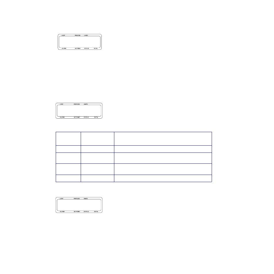
l01 Set point r
b 25 ˚C
l01 Mode r
bmanual
l01 Heat outputr
b 0%