Control data signals, Inputs, Triggers – ALLIED Vision Technologies Stingray F-504 User Manual
Page 98: Control and video data signals
Camera interfaces
STINGRAY Technical Manual V4.4.4
96
Control data signals
The inputs and outputs of the camera can be configured by software. The dif-
ferent modes are described below.
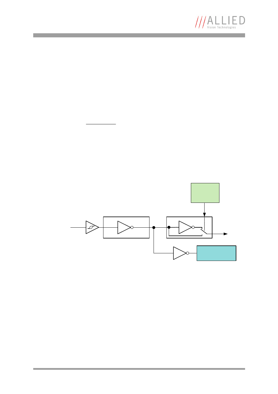
Inputs
The optocoupler inverts all input signals. Inversion of the signal is controlled
via the IO_INP_CTRL1..2 register (see
Table 22: Advanced register: Input con-
Triggers
All inputs configured as triggers are linked by AND. If several inputs are being
used as triggers, a high signal must be present on all inputs in order to gen-
erate a trigger signal. Each signal can be inverted. The camera must be set
to external triggering to trigger image capture by the trigger signal.
Note
For a general description of the inputs and warnings see
the Hardware Installation Guide, Chapter STINGRAY input
description.
Figure 45: Input block diagram
Input
Polarity
selectable
via software
Input state
Opto-
Coupler
Input signal