Flow diagram of defect pixel correction, Figure 66: defect pixel, Correction: build and store – ALLIED Vision Technologies Stingray F-504 User Manual
Page 144
Description of the data path
STINGRAY Technical Manual V4.4.4
142
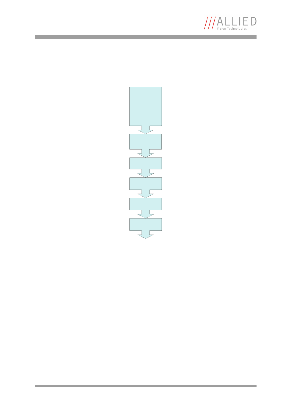
Flow diagram of defect pixel correction
The following flow diagram illustrates the defect pixel detection:
Figure 66: Defect pixel correction: build and store
Note
While building defect pixel correction data or uploading
them from host, the defect pixel correction data are
stored volatile in FPGA.
Optional you can store the data in a non-volatile memory
(Set MemSave to 1).
Note
Configuration
To configure this feature in an advanced register: See
142: Advanced register: Defect pixel correction
Set resolution to
Format_7 Mode_x
Or
Set resolution to
Format_7 Mode_0
when using fixed
modes.
Set AOI to max.
Choose threshold
Set BuildDPData
to 1
Set ON_OFF to 1
Optional:
Set MemSave to 1
Set values for
shutter, gain
to max.