Description of the data path, Block diagrams of the cameras, Black and white cameras – ALLIED Vision Technologies Stingray F-504 User Manual
Page 117: Chapter, Figure 52: block diagram b/w camera, Stingray technical manual v4.4.4
Description of the data path
STINGRAY Technical Manual V4.4.4
115
Description of the data path
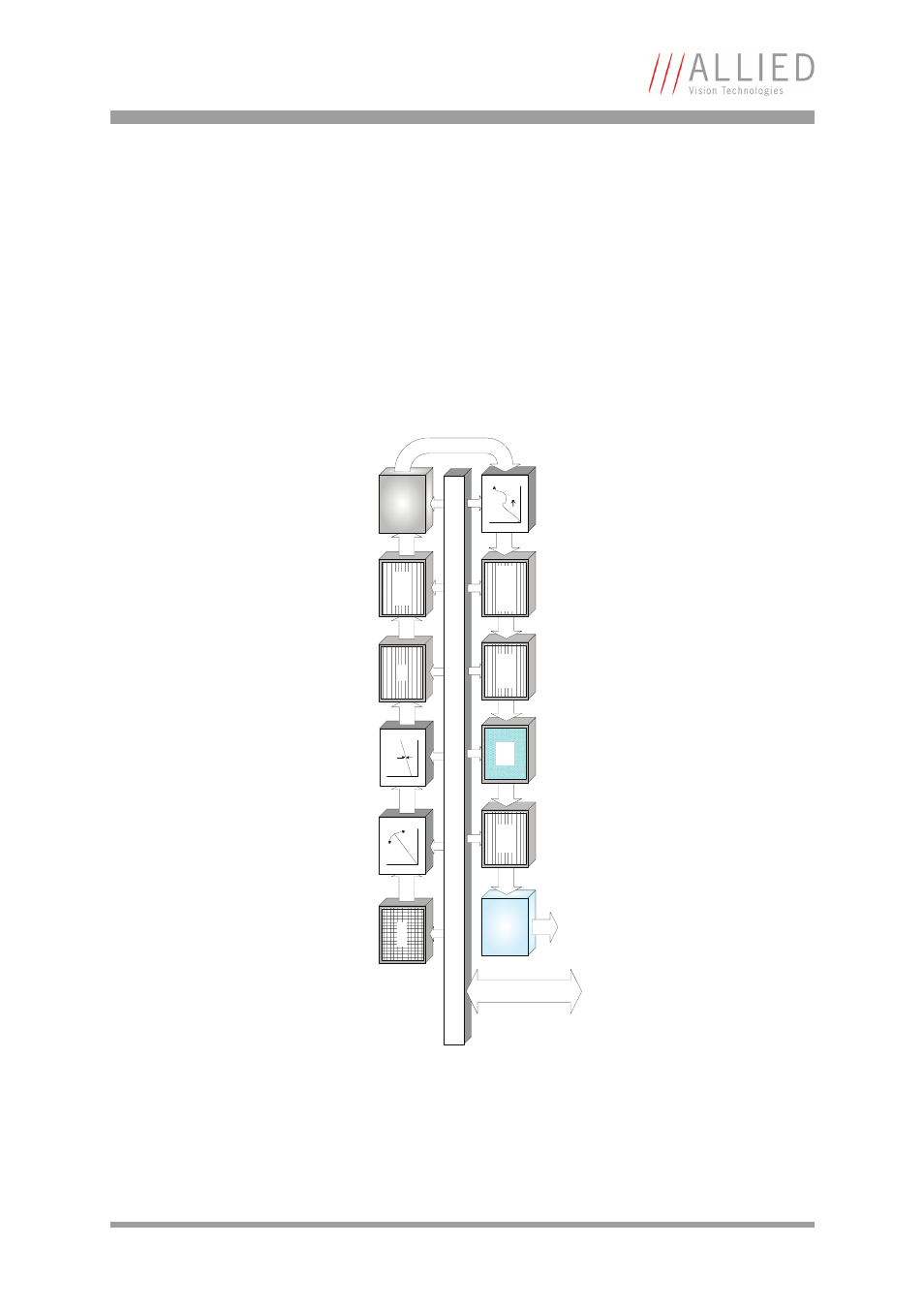
Block diagrams of the cameras
The following diagrams illustrate the data flow and the bit resolution of
image data after being read from the CCD sensor chip in the camera. The indi-
vidual blocks are described in more detail in the following paragraphs. For
sensor data see Chapter
Black and white cameras
Figure 52: Block diagram b/w camera
Sensor
Ana
log
Gain
Ana
log
Offset
Ana
log
AD
C
IEEE 1394b
interface
1394b
14 bit
Horizontal
mirror
14 bit
Shading
correction
Camera control
HIROSE I/O
RS232
8 B
it
Frame
memory
16
bit
HS
NR
control
14
bi
t
Horizontal
masking
14
bit
Horizontal
sub-sampling
14 bit
LUT
12
10
14 bit
Setting LUT = OFF effectively makes full use of the 14 bit by bypassing the
LUT circuitry; setting LUT = ON means that the most significant 12 bit of the
14 bit are used and further down converted to 10 bit.