Stingray board level: dimensions, Figure 37: stingray board level dimensions, Camera dimensions – ALLIED Vision Technologies Stingray F-504 User Manual
Page 88: Pixel 1,1 sensor - pin1, Stingray technical manual v4.4.4
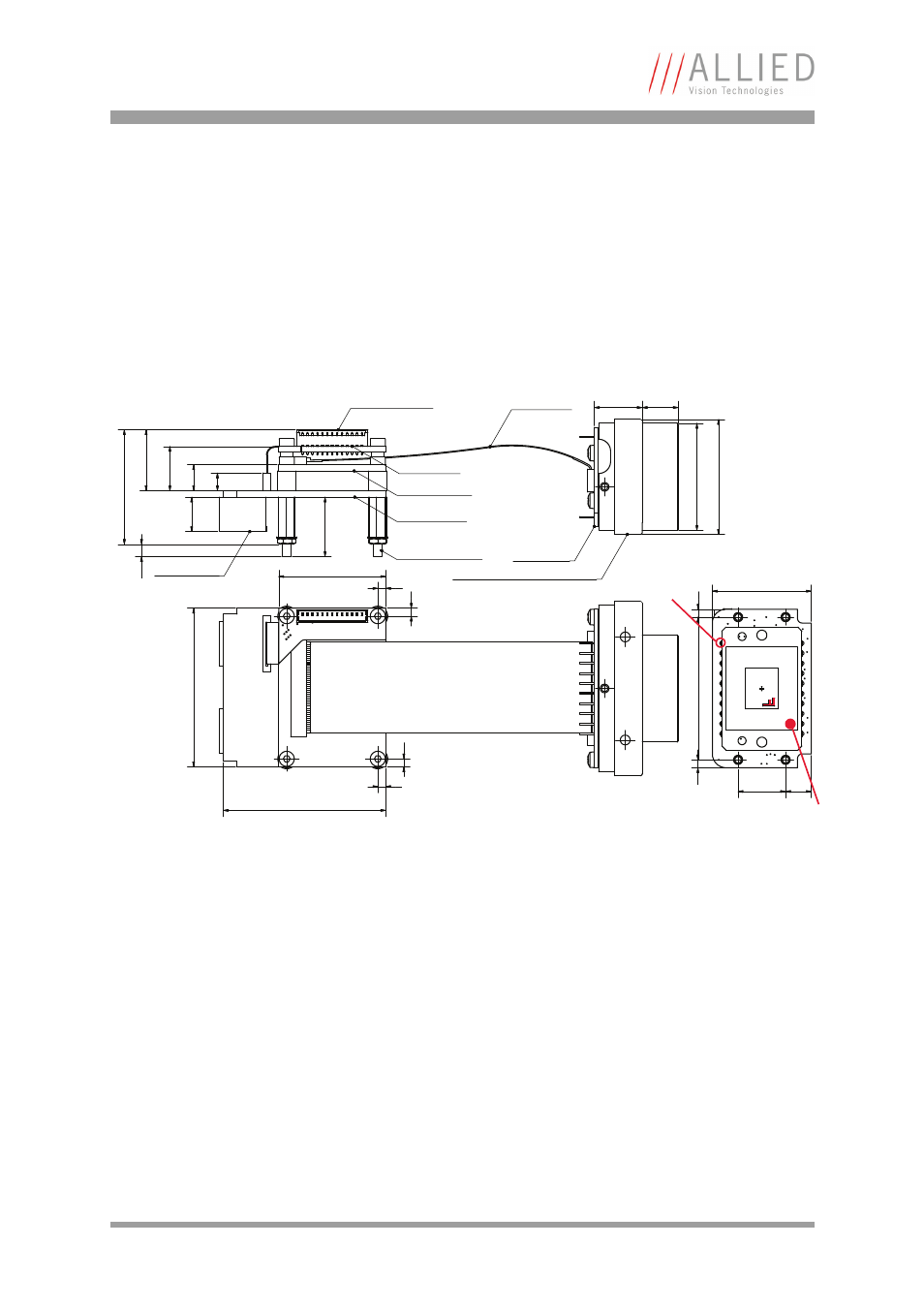
Camera dimensions
STINGRAY Technical Manual V4.4.4
86
Stingray board level: dimensions
Figure 37: Stingray board level dimensions
sensor board
1 = GND (for RS232, Ext PWR)
2 = Ext PWR input
(PWR output on demand)
3 = Output 4
4 = Input 1
5 = Output 3
6 = Output 1
FFC45 cable length:
-----------------------------
FFC45 L = 56 mm K7500307
FFC45 L = 110 mm K7500318
FFC45 cable
2
2x HOLE
2.9mm PTH
2.3 mm
PTH
2.3 mm
PTH
2
41
4
0
2
IO-AD-Board
processor board
interface board
2x IEEE 1394b
25
2
2
8
.7
1
5
4
.5
6
.6
1
1
.2
1
5
.4
27
1
13
spacer M2x10 (4x)
7 = GND (for Inputs)
8 = RxD 9 = TxD
10 = Power Input
(for Output ports)
11 = Input 2
12 = Output 2
13 = Cable Shield
12
2
8
.9
3
.1
13-pole I/O connector:
[Molex 1.25mm Pitch PicoBlade Wire-to-Board Header (53047-1310)]
----------------------------------------------------------------------------------
13-pole connector
9.1
Q
2
7
2
9
front flange with C-Mount adapter
3
6
2
6.5
12
Pixel 1,1
Sensor - Pin1