Color cameras, Figure 53: block diagram, Color camera – ALLIED Vision Technologies Stingray F-504 User Manual
Page 118: Description of the data path, Stingray technical manual v4.4.4
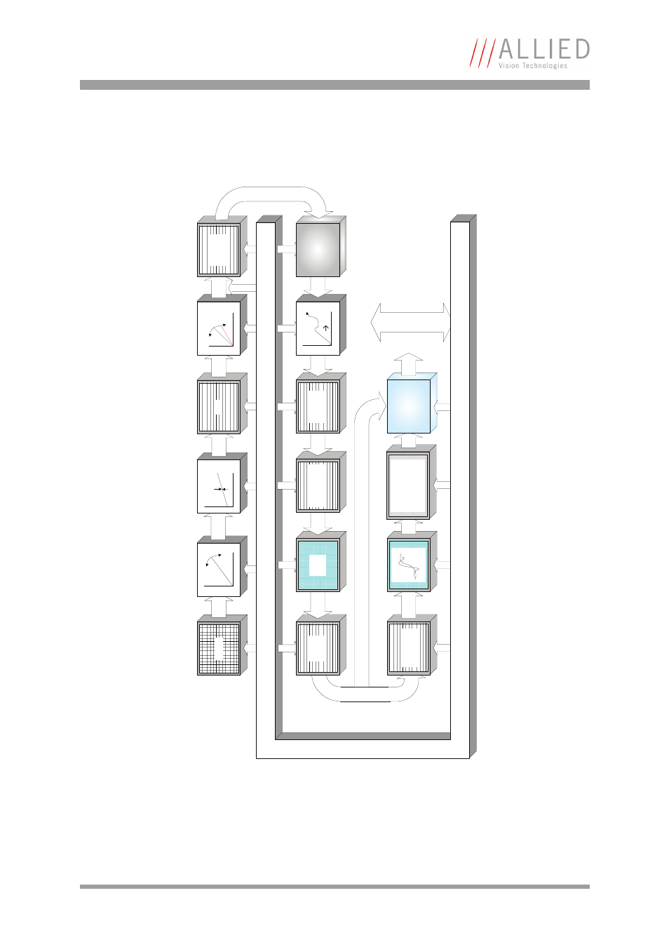
Description of the data path
STINGRAY Technical Manual V4.4.4
116
Color cameras
Setting LUT = OFF effectively makes full use of the 14 bit by bypassing the
LUT circuitry; setting LUT = ON means that the most significant 12 bit of the
14 bit are used and further down converted to 10 bit.
Figure 53: Block diagram color camera
Sensor
Analog
Gain
Analog
Offset
Analog
14 bi
t
White balance
14 bit
Horizontal
mirror
16 bit
HIROSE I/O
RS232
Test-Pattern
Color
interpolation
8 b
it
Sharpness
8 b
it
Hue
Saturation
Color correction
Color conversion
8 b
it
IEEE 1394b
interface
139
4b
Camera control
Fr
am
e
memory
16 bit
HSNR
control
14 bi
t
Horizontal
sub-sampling
14 b
it
Horizontal
masking
14 bi
t
LUT
12
10
14 bit
Shading
correction
14 bit
Camera control
ADC
Ra
w8
, Ra
w1
2, Raw16
: 16
bit
This manual is related to the following products: