Defining a circular arc, 3 pa tt er n definition pa t tern def – HEIDENHAIN iTNC 530 (34049x-08) Cycle programming User Manual
Page 70
70
Using fixed cycles
2.3
Pa
tt
er
n
definition
PA
T
TERN
DEF
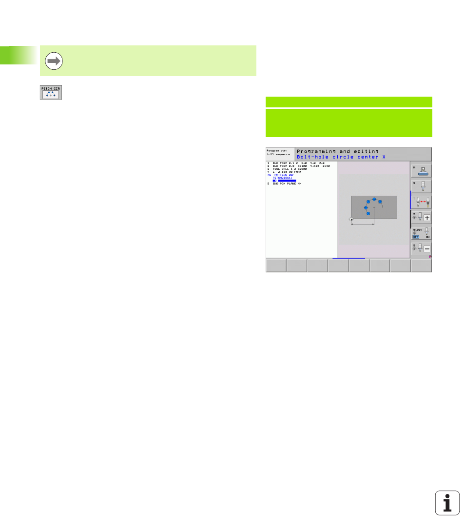
Defining a circular arc
Bolt-hole circle center X
(absolute): Coordinate of
the circle center in the X axis
Bolt-hole circle center Y
(absolute): Coordinate of
the circle center in the Y axis
Bolt-hole circle diameter
: Diameter of the bolt-hole
circle
Starting angle
: Polar angle of the first machining
position. Reference axis: Major axis of the active
machining plane (e.g. X for tool axis Z). You can enter
a positive or negative value
Stepping angle/end angle
: Incremental polar angle
between two machining positions. You can enter a
positive or negative value. As an alternative you can
enter the end angle (switch via soft key)
Number of repetitions
: Total number of machining
positions on the circle
Workpiece surface coordinate
(absolute): Enter Z
coordinate at which machining is to begin
If you have defined a workpiece surface in Z not equal to
0, then this value is effective in addition to the workpiece
surface Q203 that you defined in the machining cycle.
Example: NC blocks
10 L Z+100 R0 FMAX
11 PATTERN DEF
PITCHCIRC1 (X+25 Y+33 D80 START+45 STEP30
NUM8 Z+0)