Cycle parameters – HEIDENHAIN iTNC 530 (34049x-08) Cycle programming User Manual
Page 166
166
Fixed cycles: pocket milling / stud milling / slot milling
5.6
RECT
ANGULAR
S
T
UD
(Cy
cle
256,
DIN/ISO:
G256)
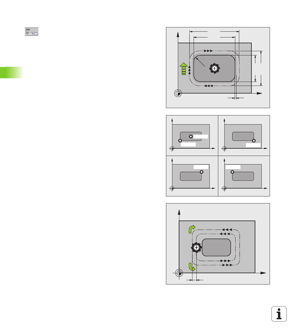
Cycle parameters
1st side length
Q218: Stud length, parallel to the
reference axis of the working plane. Input range 0 to
99999.9999
Workpiece blank side length 1
Q424: Length of the
stud blank, parallel to the reference axis of the
working plane. Enter Workpiece blank side length 1
greater than 1st side length. The TNC performs
multiple stepovers if the difference between blank
dimension 1 and finished dimension 1 is greater than
the permitted stepover (tool radius multiplied by path
overlap Q370). The TNC always calculates a constant
stepover. Input range 0 to 99999.9999
2nd side length
Q219: Stud length, parallel to the
minor axis of the working plane. Enter Workpiece
blank side length 2
greater than 2nd side length.
The TNC performs multiple stepovers if the
difference between blank dimension 2 and finished
dimension 2 is greater than the permitted stepover
(tool radius multiplied by path overlap Q370). The TNC
always calculates a constant stepover. Input range 0
to 99999.9999
Workpiece blank side length 2
Q425: Length of the
stud blank, parallel to the minor axis of the working
plane. Input range 0 to 99999.9999
Corner radius
Q220: Radius of the stud corner. Input
range 0 to 99999.9999
Finishing allowance for side
Q368 (incremental):
Finishing allowance in the working plane, is left over
after machining. Input range 0 to 99999.9999
Angle of rotation
Q224 (absolute): Angle by which
the entire stud is rotated. The center of rotation is the
position at which the tool is located when the cycle is
called. Input range -360.000 to 360.000
Stud position
Q367: Position of the stud in reference
to the position of the tool when the cycle is called:
0:
Tool position = Center of stud
1:
Tool position = Lower left corner
2:
Tool position = Lower right corner
3:
Tool position = Upper right corner
4:
Tool position = Upper left corner
X
Y
Q21
9
Q218
Q368
Q220
Q207
Q424
Q425
X
Y
X
Y
X
Y
X
Y
Q367=0
Q367=1
Q367=2
Q367=3
Q367=4
X
Y
k
Q351= 1
Q351= +1