Please note while programming, Cycle parameters, Please note while programming: cycle parameters – HEIDENHAIN iTNC 530 (34049x-08) Cycle programming User Manual
Page 360
360
Touch probe cycles: automatic datum setting
15.2
SL
O
T
CENTER
REF
PT
(Cy
cle
408,
DIN/ISO:
G408,
FCL
3
function)
Please note while programming:
Cycle parameters
Center in 1st axis
Q321 (absolute): Center of the
slot in the reference axis of the working plane. Input
range -99999.9999 to 99999.9999
Center in 2nd axis
Q322 (absolute): Center of the
slot in the minor axis of the working plane. Input
range -99999.9999 to 99999.9999
Width of slot
Q311 (incremental): Width of the slot,
regardless of its position in the working plane. Input
range 0 to 99999.9999
Measuring axis (1=1st axis / 2=2nd axis)
Q272:
Axis in which the measurement is to be made:
1
: Reference axis = measuring axis
2
: Minor axis = measuring axis
Measuring height in the touch probe axis
Q261
(absolute): Coordinate of the ball tip center (= touch
point) in the touch probe axis in which the
measurement is to be made. Input range
-99999.9999 to 99999.9999
Set-up clearance
Q320 (incremental): Additional
distance between measuring point and ball tip. Q320
is added to MP6140. Input range 0 to 99999.9999,
alternatively PREDEF
Clearance height
Q260 (absolute): Coordinate in the
touch probe axis at which no collision between touch
probe and workpiece (fixtures) can occur. Input range
-99999.9999 to 99999.9999, alternatively PREDEF
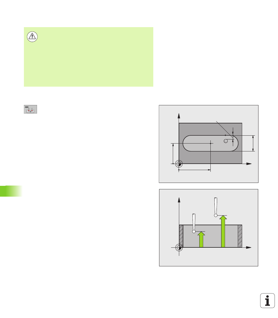
Danger of collision!
To prevent a collision between touch probe and
workpiece, enter a low estimate for the slot width.
If the slot width and the safety clearance do not permit
pre-positioning in the proximity of the touch points, the
TNC always starts probing from the center of the slot. In
this case the touch probe does not return to the clearance
height between the two measuring points.
Before a cycle definition you must have programmed a
tool call to define the touch probe axis.
X
Y
Q322
Q321
Q31
1
MP6140
+
Q320
X
Z
Q261
Q260