Effect – HEIDENHAIN iTNC 530 (34049x-08) Cycle programming User Manual
Page 295
HEIDENHAIN iTNC 530
295
11
.9
W
O
RKING
PLANE
(Cy
cle
19
, DIN/ISO:
G80,
sof
tw
ar
e
option
1)
11.9 WORKING PLANE (Cycle 19,
DIN/ISO: G80, software
option 1)
Effect
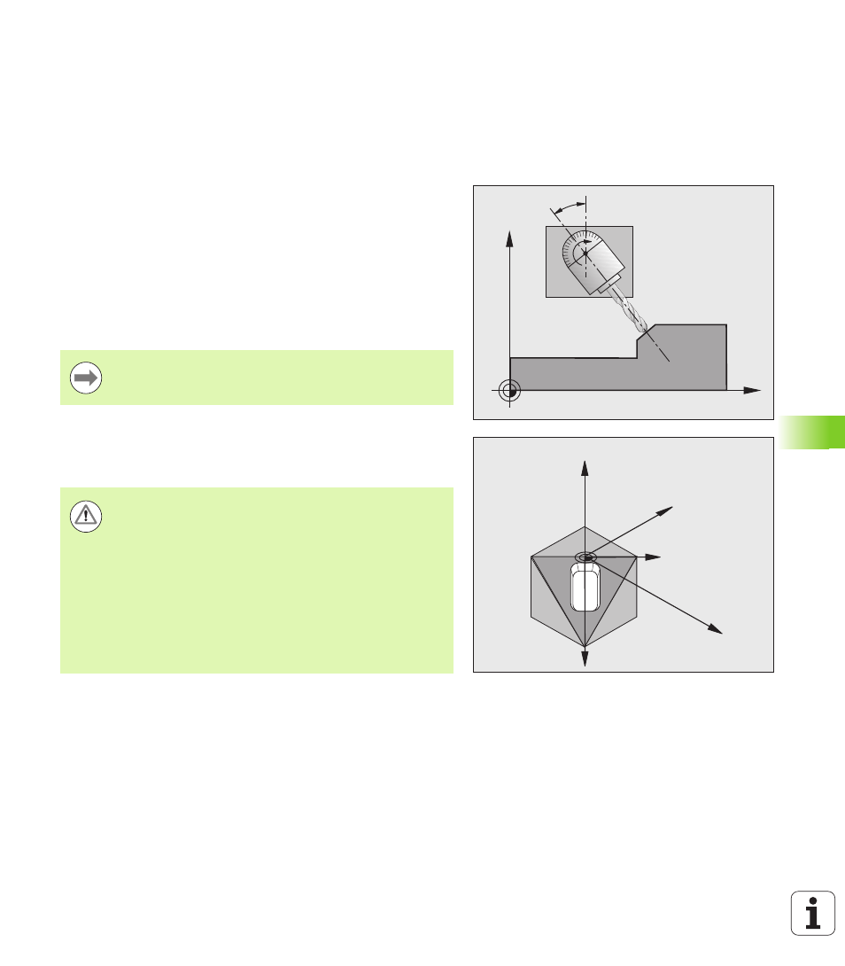
In Cycle 19 you define the position of the working plane—i.e. the
position of the tool axis referenced to the machine coordinate
system—by entering tilt angles. There are two ways to determine the
position of the working plane:
Enter the position of the rotary axes directly.
Describe the position of the working plane using up to 3 rotations
(spatial angle) of the fixed machine coordinate system. The
required spatial angle can be calculated by cutting a perpendicular
line through the tilted working plane and considering it from the axis
around which you wish to tilt. With two spatial angles, every tool
position in space can be defined exactly.
If you program the position of the working plane via spatial angles, the
TNC will calculate the required angle positions of the tilted axes
automatically and will store these in the parameters Q120 (A axis) to
Q122 (C axis).
Z
X
B
X
Z
Y
X'
Y'
Note that the position of the tilted coordinate system, and
therefore also all movements in the tilted system, are
dependent on your description of the tilted plane.
Warning!
Depending on your machine configuration, two
mathematical solutions (axis positions) are possible for a
spatial angle definition. Conduct appropriate tests on your
machine to find out which axis position the TNC software
selects in each case.
If the DCM software option is available to you, the axis
position can be displayed in the PROGRAM +
KINEMATICS view during test run (see User’s Manual for
Conversational Programming, Dynamic collision
monitoring
).