Cycle run, Please note while programming, See "basic rotation – HEIDENHAIN iTNC 530 (34049x-08) Cycle programming User Manual
Page 342: Cycle run please note while programming
342
Touch probe cycles: automatic measurement of workpiece misalignment
14.4 BA
SIC R
O
TA
TION o
ver tw
o st
uds (Cy
cle 402, DIN/ISO:
G402)
14.4 BASIC ROTATION over two
studs (Cycle 402,
DIN/ISO: G402)
Cycle run
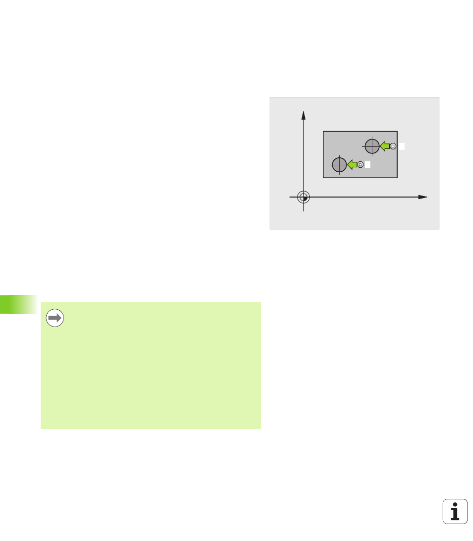
The Touch Probe Cycle 402 measures the centers of two studs. Then
the TNC calculates the angle between the reference axis in the
working plane and the line connecting the two stud centers. With the
basic rotation function, the TNC compensates the calculated value. As
an alternative, you can also compensate the determined misalignment
by rotating the rotary table.
1
Following the positioning logic (see "Executing touch probe cycles"
on page 332), the TNC positions the touch probe in rapid traverse
(value from MP6150) to the starting point
1
of the first stud.
2
Then the probe moves to the entered measuring height 1 and
probes four points to find the center of the first stud. The touch
probe moves on a circular arc between the touch points, each of
which is offset by 90°.
3
The touch probe returns to the clearance height and then positions
the probe to starting point
5
of the second stud.
4
The TNC moves the touch probe to the entered measuring
height 2
and probes four points to find the center of the second
stud.
5
Then the TNC returns the touch probe to the clearance height and
performs the basic rotation.
Please note while programming:
X
Y
1
5
Before a cycle definition you must have programmed a
tool call to define the touch probe axis.
The TNC will reset an active basic rotation at the beginning
of the cycle.
This touch probe cycle is not allowed when the tilted
working plane function is active.
If you want to compensate the misalignment by rotating
the rotary table, the TNC will automatically use the
following rotary axes:
C for tool axis Z
B for tool axis Y
A for tool axis X