4 spindle orientation (cycle 13, din/iso: g36), Cycle function, Please note while programming – HEIDENHAIN iTNC 530 (34049x-08) Cycle programming User Manual
Page 312: Cycle parameters
312
Cycles: special functions
12.4
SPINDLE
ORIENT
A
TION
(Cy
cle
13,
DIN/ISO:
G36)
12.4 SPINDLE ORIENTATION
(Cycle 13, DIN/ISO: G36)
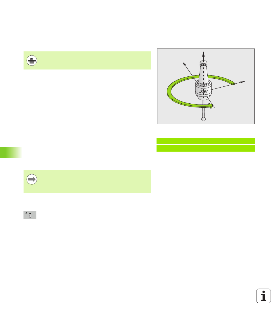
Cycle function
The TNC can control the machine tool spindle and rotate it to a given
angular position.
Oriented spindle stops are required for
Tool changing systems with a defined tool change position
Orientation of the transmitter/receiver window of HEIDENHAIN 3-D
touch probes with infrared transmission
The angle of orientation defined in the cycle is positioned to by
entering M19 or M20 (depending on the machine).
If you program M19 or M20 without having defined Cycle 13, the TNC
positions the machine tool spindle to an angle that has been set by the
machine manufacturer (see your machine manual).
Please note while programming:
Cycle parameters
Angle of orientation
: Enter the angle referenced to
the reference axis of the working plane. Input range:
0.0000° to 360.0000°
Example: NC blocks
93 CYCL DEF 13.0 ORIENTATION
94 CYCL DEF 13.1 ANGLE 180
X
Y
Z
Machine and TNC must be specially prepared by the
machine tool builder for use of this cycle.
Cycle 13 is used internally for Cycles 202, 204 and 209.
Please note that, if required, you must program Cycle 13
again in your NC program after one of the machining
cycles mentioned above.