Din and dinbin function, 4 f o rm ulas – HEIDENHAIN ND 2100G User Manual
Page 230
230
2 Installation and Specifications
2.4 F
o
rm
ulas
Din and DinBin function
The primary parallel port is configured as a general-purpose data Input/
Output (I/O) port, and does not support parallel printers.
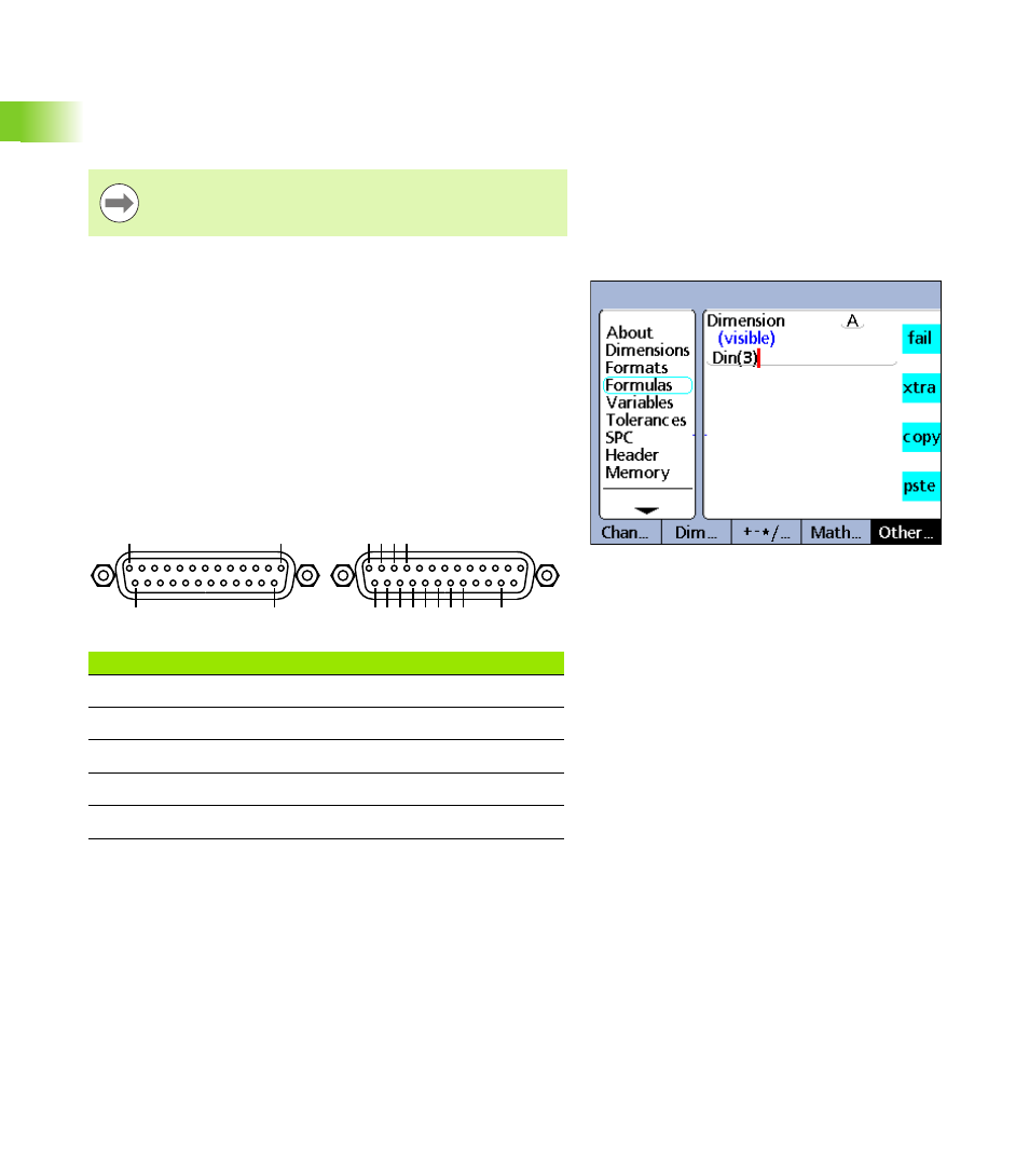
The ND 2100G uses 5 pins of the parallel port connector as the inputs
shown below. Inputs support 5 volt TTL logic levels only.
Din
Insert the Din function to read the logic level of a single parallel port
input pin or range of parallel port pins. The logic level from a single pin
can be used in a dimension formula, or the decimal equivalent of the
binary values from a range of pins can be used.
To insert the Din function:
U
Press the OTHER... soft key
U
Press the XTRA dimension key
U
Use the arrow cursor keys to highlight Din
U
Press the ENTER key
The Din pins of the parallel port connector are numbered 1 through 5.
Logic levels are referred to ground on pins 18 through 25.
Electrical characteristics of the parallel port are described
under Specifications in this chapter.
Din function.
Din
Parallel pin
1
15
2
13
3
12
4
11
5
10
Pin 13
Pin 1
Pin 25
Pin 14
Din 2 3 4 5
Din 1
Ground Reference