Centering (nulling) lvdt and hbt transducers, 3 s o ft wa re s e tu p – HEIDENHAIN ND 2100G User Manual
Page 107
ND 2100G GAGE-CHEK
107
2
.3
S
o
ft
wa
re
s
e
tu
p
Centering (nulling) LVDT and HBT transducers
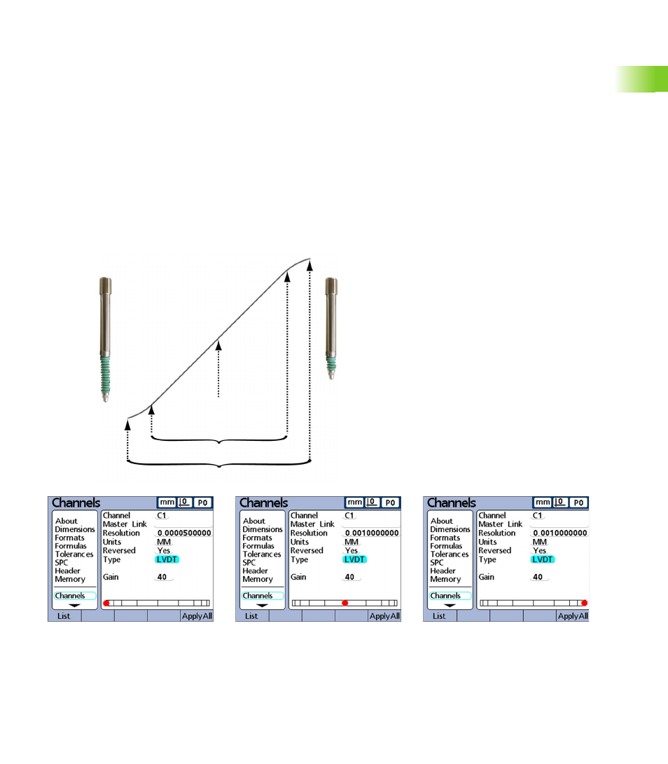
Transducer outputs are most linear in the central portion of their total
range of movement. Each LVDT and HTB transducer must be
positioned at the center of its range of movement (nulled) in the gage
and against a nominal reference surface to provide the most accurate
measurements. The bar graph at the bottom of the transducer
Channel setup screens display the relative position of the transducer
tips from one extreme of movement to the other and is used to null
transducers as shown below.
Prior to conducting measurements the transducer gain must be
calibrated as described on page 106, and then the transducer must be:
Secured in the gage
Positioned against the nominal reference surface
Adjusted in the gage to null against the nominal reference surface
Locked in place
Transducer fully extended.
Transducer nulled.
Transducer fully compressed.
Transducer
fully extended
Transducer
nulled against
nominal surface
Transducer
fully compressed
Linear range
Total range