Slec (segmented linear error correction), 3 s o ft wa re s e tu p – HEIDENHAIN ND 2100G User Manual
Page 116
116
2 Installation and Specifications
2
.3
S
o
ft
wa
re
s
e
tu
p
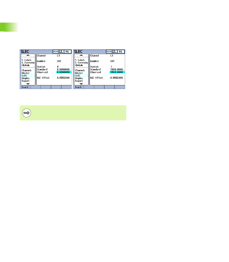
The standard and observed values at the two ends of the
measurement range are entered as data for stations 0 and 1 in the
SLEC setup screen. The standard and observed values at the
beginning of the range are 0 because this end of the standard is the
measurement reference. These zero values are entered into Station 0.
The standard and observed values at the end of the range are 1500
and 1520 respectively in our example shown below, indicating a
linearity error of 20 over the entire range of measurement. These
values are entered into Station 1.
When the procedure is complete and setup data are entered, a
correction coefficient will be calculated for the input device.
SLEC (Segmented linear error correction)
SLEC compensates for channel input nonlinearities by applying
correction coefficients only to the segments that require them. These
SLEC correction coefficients are created by the ND 2100G system
using data provided by the user in the SLEC setup screen. The SLEC
setup data provided by the user consists of nominal and measured
values of a standard, or standards that cover the entire channel input
range.
The measurements divide the channel input range into as many as 60
user defined segments. The diagram on the next page shows nominal
(standard) values compared to measured (observed) values. The
deviation (difference between standard and observed) is shown as a
graph. Segments are defined here as any straight line on the graph,
beginning with segment zero.
The LEC setup procedure is a subset of steps required for
SLEC setup and requires a repeatable machine zero and
only the first and last station entries.