Interlogix NS3550-8T-2S User Manual User Manual
Page 303
User’s Manual of NS3550-8T-2S
303
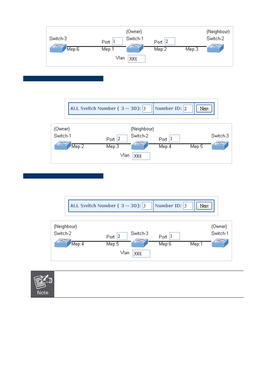
Set ERPS Configuration on Switch 2
Connect PC to switch 2 directly; don’t connect to port 1 & 2
Logging on the Switch 2 and click “Ring > Ring Wizard”
Set “All Switch Number” = 3 and “Number ID” = 2; click “Next” button to set the ERPS configuration for Switch 2.
Set “MEP3” = Port2, “MEP4” = Port1 and VLAN ID = 3001; click “Set” button to save the ERPS configuration for Switch 2.
Set ERPS Configuration on Switch 3
Connect PC to switch 3 directly; don’t connect to port 1 & 2
Logging on the Switch 3 and click “Ring > Ring Wizard”
Set “All Switch Number” = 3 and “Number ID” = 3; click “Next” button to set the ERPS configuration for Switch 3.
Set “MEP5” = Port2, “MEP6” = Port1 and VLAN ID = 3001; click “Set” button to save the ERPS configuration for Switch 3.
To avoid loop, please don’t connect switch 1, 2 & 3 together in the ring topology before configuring the
end of ERPS .
Follow the configuration or ERPS wizard to connect the Switch 1, 2 & 3 together to establish ERPS application:
MEP2 ←→ MEP3 = Switch1 / Port2 ←→ Switch2 / Port2
MEP4
←→
MEP5 = Switch2 / Port1 ←→ Switch3 / Port2
MEP1
←→
MEP6 = Switch1 / Port1 ←→ Switch3 / Port1