10 vlan setting example, 1 two separate 802.1q vlan – Interlogix NS3550-8T-2S User Manual User Manual
Page 111
User’s Manual of NS3550-8T-2S
111
4.6.10 VLAN setting example:
- Separate VLAN
- 802.1Q VLAN Trunk
- Port Isolate
4.6.10.1 Two separate 802.1Q VLAN
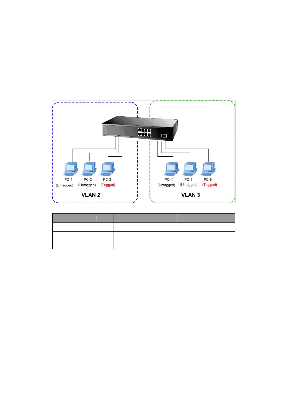
The diagram shows how the Industrial Managed Switch handle Tagged and Untagged traffic flow for two VLANs. VLAN Group 2
and VLAN Group 3 are separated VLAN. Each VLAN isolates network traffic so only members of the VLAN receive traffic from
the same VLAN members. The screen in
Figure 4-6-8
appears and
Table 4-1
describes the port configuration of the Industrial
Managed Switch
.
Figure 4-6-8:
Two Separate VLAN Diagram
VLAN Group
VID
Untagged Members
Tagged Members
VLAN Group 1
1
Port-7 ~ Port-10
N/A
VLAN Group 2
2
Port-1,Port-2
Port-3
VLAN Group 3
3
Port-4,Port-5
Port-6
Table 4-1:
VLAN and Port Configuration
The scenario described as follow:
Untagged packet entering VLAN 2
1.
While [PC-1] transmitting an untagged packet enters Port-1, the Managed Switch will tag it with a VLAN Tag=2.
[PC-2]
and [PC-3] will receive the packet through Port-2 and Port-3.
2.
[PC-4],[PC-5] and [PC-6] receive no packet.
3.
While the packet leaves Port-2, it will be stripped away its tag becoming an untagged packet.
4.
While the packet leaves Port-3, it will keep as a tagged packet with VLAN Tag=2.
Tagged packet entering VLAN 2
5.
While [PC-3] transmit a tagged packet with VLAN Tag=2 enters Port-3, [PC-1] and [PC-2] will receive the packet
through Port-1 and Port-2.
6.
While the packet leaves Port-1 and Port-2, it will be stripped away its tag becoming an untagged packet.
Untagged packet entering VLAN 3
1. While
[PC-4]
transmit an untagged packet enters Port-4, the switch will tag it with a VLAN Tag=3. [PC-5] and
[PC-6]
will receive the packet through Port-5 and Port-6.
2.
While the packet leaves Port-5, it will be stripped away it tag becoming an untagged packet.
3.
While the packet leaves Port-6, it will keep as a tagged packet with VLAN Tag=3.