0x60c0, 0x60c1, 0x60c2 – Lenze E94AxHE Technology Application CiA402 Device profile User Manual
Page 133: 0x60c1/1, Interpolation
EDS94TA11010xxxx EN 1.2 - 03/2010
L
133
9400 Technology applications | CiA402 device profile
Parameter setting & configuration
Interpolated position mode
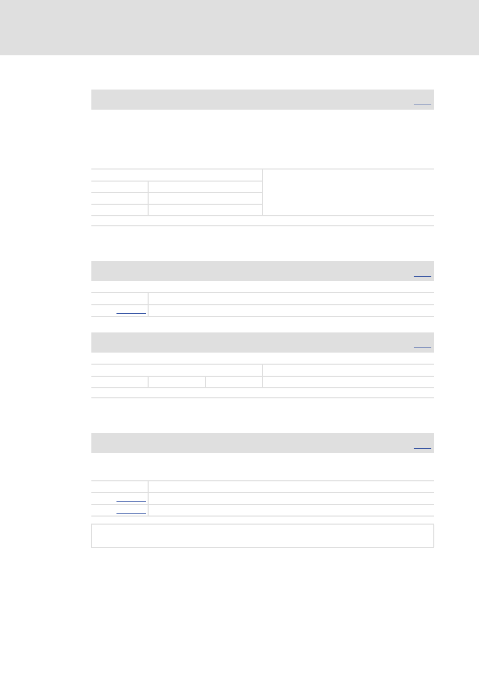
0x60C0 - Interpolation sub mode select
0x60C1 - Interpolation data record
0x60C2 - Interpolation time period
[3-13] Definition of the interpolation cycle time
Index | Name:
0x60C0 | Interpolation sub mode select
Data type: INTEGER_16
Interpolation algorithm
• If "Linear interpolation" or "Quadratic interpolation" has been selected and no feedforward control values for
speed and torque/acceleration are transmitted, it is wise to generate the feedforward values by differentiation
of the position signal (C02681, C00276).
• If "Optimized mode 1" has been selected, the feedforward control values in the application are differentiated
from the set position in the grid of the bus cycle time and then linearly interpolated to the control cycle.
(No additional differentiation functions required.)
Selection list
(Lenze setting printed in bold)
-11 Optimised mode 1
-1 Quadratic interpolation
0 Linear interpolation
;
Read access ; Write access ; CINH PLC-STOP PDO_MAP_RX PDO_MAP_TX
Index | Name:
0x60C1 | Interpolation data record
Data type: INTEGER_32
Interpolation data buffer
Subindex Name
X1
Index | Name:
0x60C1/1 | X1
Data type: INTEGER_32
Setpoint for position interpolation
Setting range
(min. value | unit | max. value)
Lenze setting
-2147483648
pos unit
2147483647 0 pos unit
;
Read access ; Write access CINH PLC-STOP ; PDO_MAP_RX PDO_MAP_TX
Index | Name:
0x60C2 | Interpolation time period
Data type: UNSIGNED_32
Interpolation cycle time
• For the communication via system bus (CANopen), the sync cycle time must also be parameterised in code
C01121.
Subindex Name
ip time units
ip time index
Interpolation cycle time s
[ ]
ip time units 10
ip time index
s
[ ]
⋅
=